
High-precision three-dimensional posture inertia measurement system and method based on MEMS (Micro Electro Mechanical Systems)

A three-dimensional attitude and inertial measurement technology, applied in directions such as navigation through velocity/acceleration measurement, which can solve the problems of low accuracy and high sensor cost

Inactive Publication Date: 2014-05-07
HARBIN INST OF TECH
View PDF2 Cites 87 Cited by
  • Summary
  • Abstract
  • Description
  • Claims
  • Application Information

AI Technical Summary

Problems solved by technology

[0003] The present invention aims to solve the problems of high cost and low precision of sensors used in existing three-dimensional attitude inertial measurement equipment

Method used


Image

  • High-precision three-dimensional posture inertia measurement system and method based on MEMS (Micro Electro Mechanical Systems)
  • High-precision three-dimensional posture inertia measurement system and method based on MEMS (Micro Electro Mechanical Systems)
  • High-precision three-dimensional posture inertia measurement system and method based on MEMS (Micro Electro Mechanical Systems)

Examples


specific Embodiment approach 1

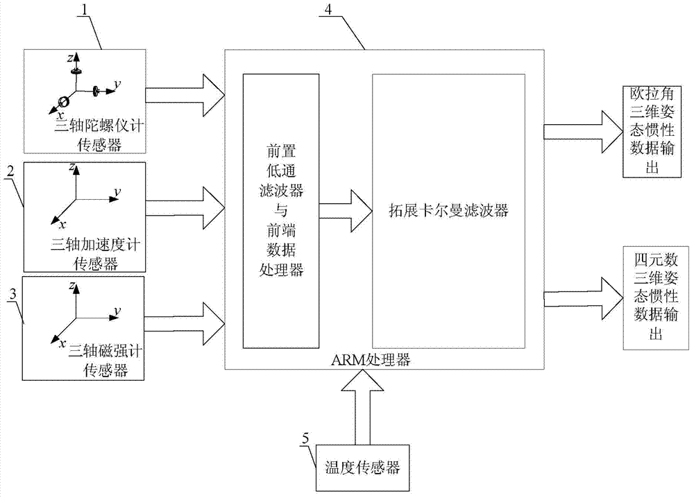
[0014] Specific implementation mode one: refer to figure 1 Specifically illustrate the present embodiment, a kind of MEMS-based high-precision three-dimensional attitude inertial measurement system described in the present embodiment, it comprises microelectromechanical type inertial measurement device, it also comprises ARM processor 4 and temperature sensor 5,

[0015] The MEMS inertial measurement device includes a three-axis gyroscope sensor 1, a three-axis accelerometer sensor 2 and a three-axis magnetometer sensor 3,

[0016] The three-axis gyroscope sensor 1 is used to measure and obtain the angular velocity, and send the angular velocity data obtained by the measurement to the ARM processor 4,

[0017] The three-axis accelerometer sensor 2 is used to measure and obtain the acceleration, and the acceleration data obtained by the measurement is sent to the ARM processor 4,

[0018] The three-axis magnetometer sensor 3 is used to measure and obtain the magnetic intensity...

specific Embodiment approach 2

[0021] Embodiment 2: The difference between this embodiment and the MEMS-based high-precision three-dimensional attitude inertial measurement system described in Embodiment 1 is that the ARM processor 4 is realized by the model STM32F405.

specific Embodiment approach 3

[0022] Embodiment 3: The difference between this embodiment and the MEMS-based high-precision three-dimensional attitude inertial measurement system described in Embodiment 1 is that the three-axis gyroscope sensor 1 is implemented with a model of MPU6050.


PUM


Abstract

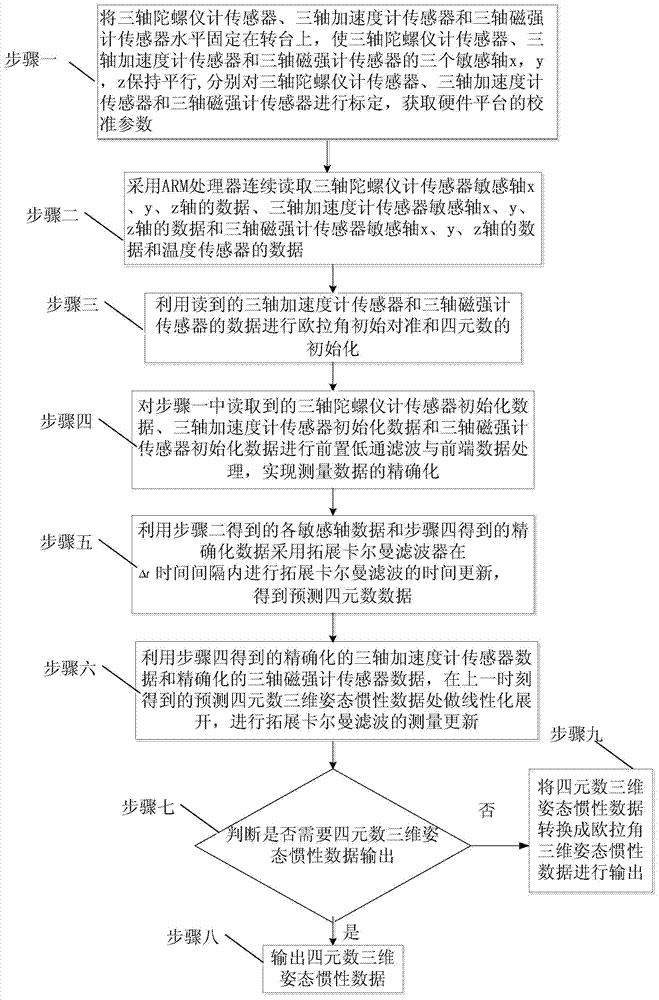
The invention discloses a high-precision three-dimensional posture inertia measurement system and method based on MEMS (Micro Electro Mechanical Systems), which relate to a high-precision three-dimensional posture inertia measurement method. The system and the method disclosed by the invention aim for solving the problems that the existing three-dimensional posture inertia measurement equipment is low in cost and low in precision due to adoption of a sensor. A three-axis gyroscope sensor is used for sending measured angular speed data to an ARM (Advanced RISC Machines) processor; a three-axis accelerometer sensor is used for sending measured acceleration data to the ARM processor; a three-axis magnetometer sensor is used for sending measured magnetic strength data to the ARM processor; a temperature sensor is used for measuring and sending obtained temperature excursion data of the three-axis gyroscope sensor to the ARM processor; the ARM processor is used for processing the received data by means of front low-pass digital filtration, front-end data processing and expansion Kalman filtration respectively so as to obtain Euler angle three-dimensional posture inertia data or quaternion three-dimensional posture inertia data. The system and the method disclosed by the invention can be applied to the field of navigation control.

Description

technical field [0001] The invention relates to a space three-dimensional attitude measurement method, in particular to a MEMS-based high-precision three-dimensional attitude inertial measurement method. Background technique [0002] UAVs, robots, mechanical gimbals, vehicles and ships, virtual reality, human motion analysis, etc. have all achieved rapid development in recent years. In these applications, the autonomous measurement of three-dimensional attitude and orientation is extremely important. Among the existing three-dimensional attitude and orientation sensors, MEMS sensors are low in cost, but the measurement data cannot meet the accuracy requirements of the above applications due to large errors such as zero bias and temperature drift; while some IMU modules can be used in terms of accuracy It meets the requirements, but the high cost limits its practical application. Contents of the invention [0003] The invention aims to solve the problems of high cost and ...

Claims


Application Information

Patent Timeline
Patent Type & Authority Applications(China)
IPC IPC(8): G01C21/16
CPCG01C21/16
Inventor 胡庆雷肖冰陈卓
Owner HARBIN INST OF TECH
Learn More