Starter

一种起动器、动铁心的技术,应用在发动机的起动、继电器、发动机用电动机起动等方向,能够解决高加工精度、成本上升、空间部负压易产生偏差等问题,达到抑制驱动弹簧挠曲、啮合性提高、防止啮合不良的效果

Inactive Publication Date: 2014-05-07
MITSUBISHI ELECTRIC CORP
View PDF6 Cites 2 Cited by
  • Summary
  • Abstract
  • Description
  • Claims
  • Application Information

AI Technical Summary

Problems solved by technology

[0011] However, in the structure of the electromagnetic switch of the starter described in Patent Document 2, since the space between the two shafts is processed to improve airtightness, the negative pressure in the space is likely to vary, and the kinetic energy of the plunger is suppressed. The effect is unstable, so the effect of improving the meshing performance of the pinion and the ring gear cannot be obtained stably
[0012] In addition, since the deflection of the drive spring is indirectly suppressed by suppressing the suction (movement) speed of the plunger, in order to fully exert the above-mentioned air damper function, a very high space is required between the two shafts. The airtightness of the machine requires high machining accuracy, which is the main reason for the increase in cost.

Method used


Image

  • Starter
  • Starter
  • Starter

Examples


Embodiment approach 1

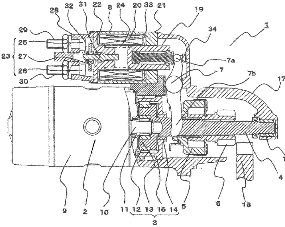
[0056] figure 1 is a partial sectional view showing the basic structure of the starter according to Embodiment 1 of the present invention, figure 2 yes figure 1 A cross-sectional view of the main part of the plunger in .

[0057] Such as figure 1 As shown, the starter 1 is composed of a motor 2, a reduction gear 3, an output shaft 4, a pinion 6, an electromagnetic switch 8, etc., wherein the motor 2 generates a rotational force, and the reduction gear 3 decelerates the rotational speed of the motor 2, The output shaft 4 is driven by the motor 2 through the reduction gear 3 , the pinion 6 and the clutch 5 are integrally arranged on the output shaft 4 , and the electromagnetic switch 8 directs the clutch 5 and the pinion 6 to the motor through the shift lever 7 . in the opposite direction ( figure 1 on the right side) and turn on and off the energizing circuit of motor 2.

[0058] The motor 2 is a well-known DC motor, which has an excitation system (not shown) formed by ar...

Embodiment approach 2

[0105] Figure 5 It is a perspective view of main parts showing the flange portion of the hook portion 34 according to Embodiment 2 of the present invention.

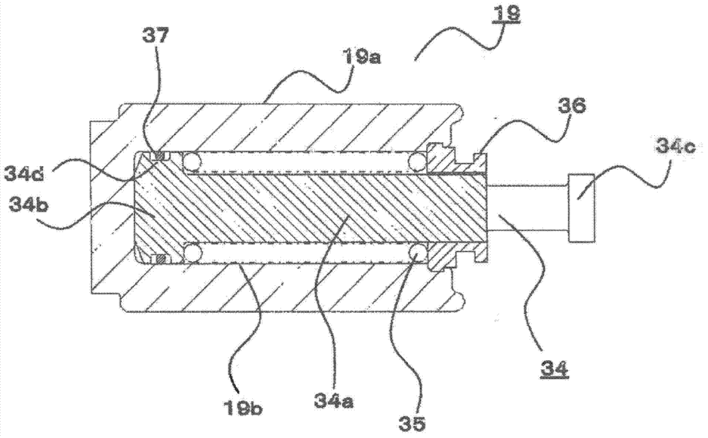
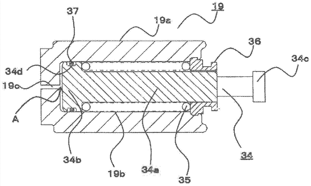
[0106] Figure 6A and Figure 6B is a sectional view of main parts of the plunger according to Embodiment 2 of the present invention, wherein Figure 6A It is a cross-sectional view showing a state in which the movable iron core moves while flexing the drive spring, Figure 6B It is a cross-sectional view showing a state in which the hook moves while releasing the drive spring.

[0107] In Embodiment 2, the elastic body 37 is annularly provided on the entire circumference of the first annular groove 34d provided in the hook portion 34. Figure 5 As shown, a second flow path groove portion 34g is formed in the first annular groove portion 34d. The second flow path groove portion 34g extends in the axial direction and has a depth greater than that of the first annular groove portion 34d. A second flow path area enlar...


PUM


Abstract

A starter is disposed with an elastic body which generates slide resistance between the inner circumferential surface of a cylinder hole of a movable core and a first annular groove section of a flange section of a hook and the starter has an air damper function; and consequently, the effect of suppressing compression of a drive spring can be sufficiently obtained without reducing the suction speed of a plunger as much as possible and an engine can be rapidly started up.

Description

technical field [0001] The present invention relates to a structure of a starter for starting an engine. Background technique [0002] Conventionally, there is known a starter in which a spring is disposed between a rod for pushing out a pinion and a plunger in order to reliably open and close a movable contact and a fixed contact of an electromagnetic switch. In this type of starter, the plunger is attracted by the operation of the electromagnetic switch, and the pinion is pushed out by the rod engaged with the plunger, so that the pinion meshes with the ring gear (for example, Patent Document 1). . [0003] In the above-mentioned starter, the attraction force to the plunger is strong relative to the inertia of the pinion, the overrunning clutch axially pushed out together with the pinion, and the rod. As the plunger begins to be attracted, the spring begins to deflect. [0004] If the spring starts to flex as soon as the plunger starts to move, the contacts close before...

Claims


Application Information

Patent Timeline
Patent Type & Authority Applications(China)
IPC IPC(8): F02N11/00F02N15/06
CPCF02N15/067F02N11/00F02N11/087H01H51/065Y10T74/13Y10T74/132
Inventor 木村元昭
Owner MITSUBISHI ELECTRIC CORP
Why Eureka
Try Eureka