Eureka AIR delivers breakthrough ideas for toughest innovation challenges, trusted by R&D personnel around the world.

Humidification stirring system

A stirring system and stirring blade technology, which are applied in mixers with rotating stirring devices, dissolving, packaging, etc., can solve the problems of weak conveying and stirring function of spiral blades, easy wear of casings and blades, and complex structure, etc., and reach the scope of application. Wide, prevent wet material agglomeration, compact and simple effect

Inactive Publication Date: 2014-05-07
黄山晶品建筑集料科技有限公司
View PDF6 Cites 10 Cited by
  • Summary
  • Abstract
  • Description
  • Claims
  • Application Information

AI Technical Summary

Problems solved by technology

[0002] Single-shaft or double-shaft humidifying mixers are two common humidifying mixers at present, which are mainly used for humidifying and stirring powdery solid particle materials such as fly ash and dry ash during the transportation process, specifically single-shaft or double-shaft humidifying The mixer stirs the solid particle materials and water entering the box through the high-speed rotating helical blades arranged on the rotating shaft, and transports them to the discharge port of the box, which can prevent the waste of solid particle materials and the pollution of the working environment caused by flying dust. However, it has problems such as complex structure, high power consumption, weak conveying and stirring function of the helical blade, and easy wear and tear of the casing and blades.

Method used


Image

  • Humidification stirring system
  • Humidification stirring system
  • Humidification stirring system

Examples


Embodiment Construction

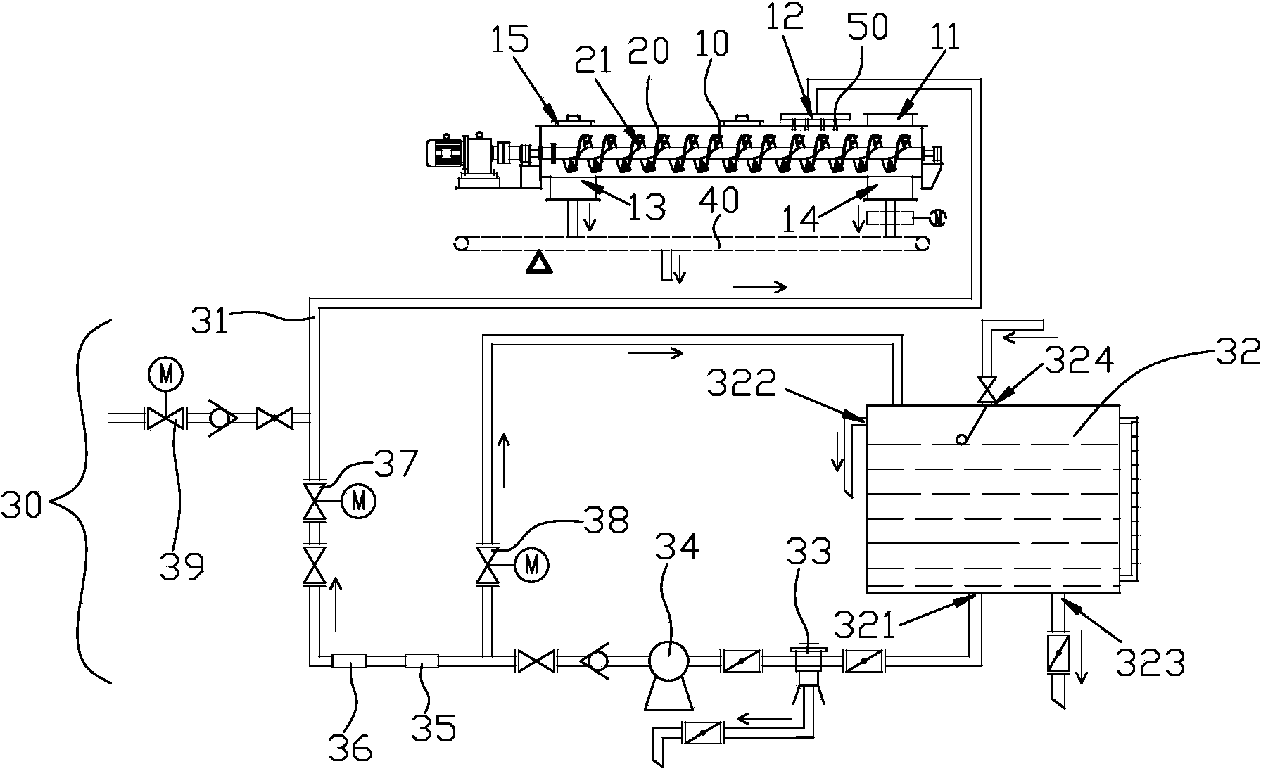
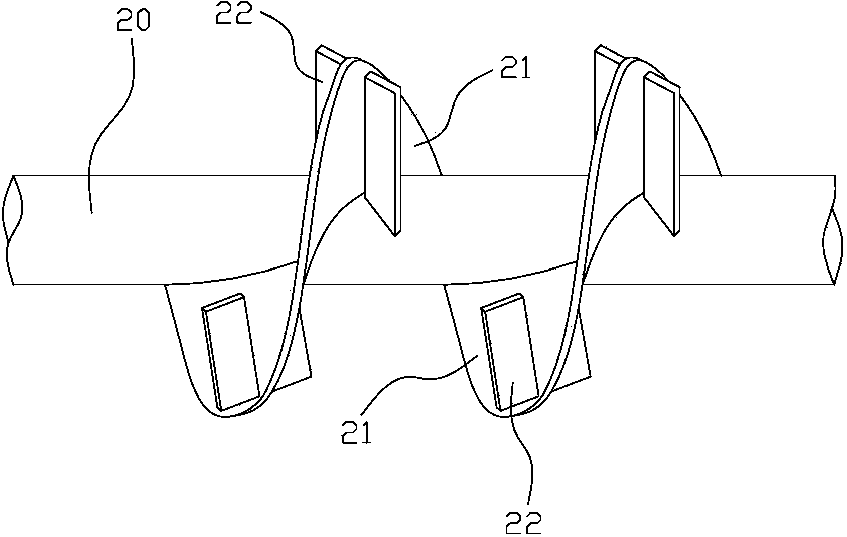
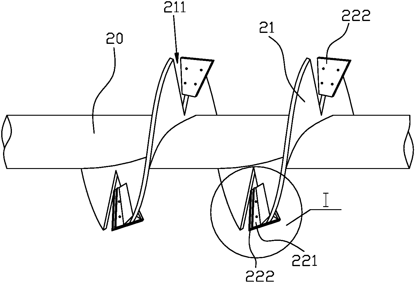
[0009] A humidification mixing system, such as Figure 1-4 As shown, it includes a box body 10 and a rotating shaft 20 arranged on the box body 10. The upper part of one end of the box body 10 is provided with a solid particle material inlet 11 and a water spray port 12, and the lower part of the other end of the box body 10 is provided with a solid particle material. The wet material outlet 13 after the material and water are mixed, the water spray port 12 is connected with the water pipe 31 of the water spray device 30, and the shaft body 20 in the box body 10 is fixedly provided with a helical blade 21, and the helical blade 21 Stirring blades 22 are arranged on at least one side of the blade surface, and the blade surfaces of the stirring blades 22 and the blade surfaces of the spiral blades 21 at their positions are arranged at an angle. The helical blade 21 and the stirring blade 22 have the functions of pushing the material forward and cleaning the wet material at the b...


PUM


Abstract

The invention discloses a humidification stirring system. The humidification stirring system comprises a box and a rotating shaft arranged on the box, wherein the upper part of one end of the box is provided with a solid particle material inlet and a water injection nozzle, the lower part of the other end of the box is provided with a solid particle material and water mixed wet material outlet, the water injection nozzle is communicated with a water pipe of a water injection device, a spiral blade is fixedly arranged on a shaft body of the rotating shaft, which is located in the box, a mixing blade is arranged on the blade surface of the spiral blade, an included angle is formed between the blade surface of the mixing blade and the blade surface of the spiral blade where the mixing blade is located, and the spiral blade and the mixing blade have the effects of pushing materials to move forwards and cleaning wet materials at the bottom of the box while being used for stirring and mixing the materials and water, so that the wet material clustering is avoided, the uniformity of the wet material mixing is further improved, and the reliability of system operation is ensured. Meanwhile, as the structure of the humidification stirring system is compact and simple, the humidification stirring system is low in installed power and energy consumption. The humidification stirring system disclosed by the invention is wide in application range and can be applied to the humidification and conveying of various types of solid particle materials.

Description

technical field [0001] The invention relates to the field of chemical machinery, in particular to a humidifying and stirring system for solid particle materials. Background technique [0002] Single-shaft or double-shaft humidifying mixers are two common humidifying mixers at present, which are mainly used for humidifying and stirring powdery solid particle materials such as fly ash and dry ash during the transportation process, specifically single-shaft or double-shaft humidifying The mixer stirs the solid particle materials and water entering the box through the high-speed rotating helical blades arranged on the rotating shaft, and transports them to the discharge port of the box, which can prevent the waste of solid particle materials and the pollution of the working environment caused by flying dust. However, it has problems such as relatively complex structure, high power consumption, weak conveying and stirring function of the helical blade, and easy wear and tear of t...

Claims


Application Information

Patent Timeline
Patent Type & Authority Applications(China)
IPC IPC(8): B01F7/08B01F3/12B65G33/14
Inventor 叶浩荣宋昌道
Owner 黄山晶品建筑集料科技有限公司
Why Eureka
Eureka Blog
Learn More