Acquisition amplifier circuit for floating weak current
What is Al technical title?
Al technical title is built by PatSnap Al team. It summarizes the technical point description of the patent document.
A technique of amplifying circuits and weak currents, applied in the field of electricity, can solve problems affecting the linearity of measured values, distortion, and weakening current signals, etc., and achieve the effect of facilitating signal processing
Active Publication Date: 2016-04-27
TAIYUAN UNIV OF TECH
View PDF3 Cites 0 Cited by
Summary
Abstract
Description
Claims
Application Information
AI Technical Summary
This helps you quickly interpret patents by identifying the three key elements:
Problems solved by technology
Method used
Benefits of technology
Problems solved by technology
This creates a problem: the measurement circuit usually has a certain input impedance, and this impedance is introduced into the loop of the signal of the circuit under test, which will weaken the current signal to be measured
If the input impedance of the measurement circuit is affected by the change of the current signal, the measured value will not only have a certain error, but also show nonlinear characteristics.
If it is amplified again, it will cause very serious distortion
[0003] At present, there are many schemes for collecting and amplifying floating weak current signals, but these schemes mainly have the following disadvantages: 1. The collection process affects the size of the current signal to be measured; 2. The amplification process affects the linearity of the measured value
The above two shortcomings lead to some distortion in the measurement results.
Method used
Image
Click on the blue label to locate the original text in one second.
Reading with bidirectional positioning of images and text.
Examples
Embodiment Construction
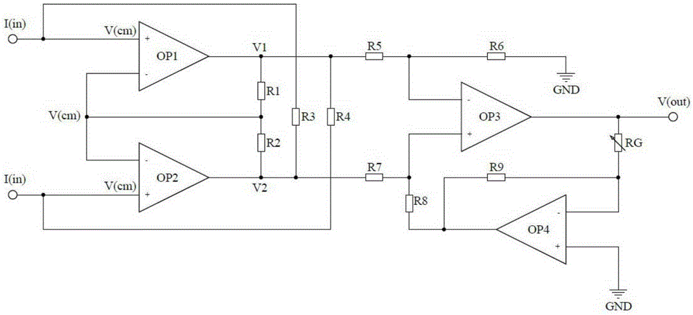
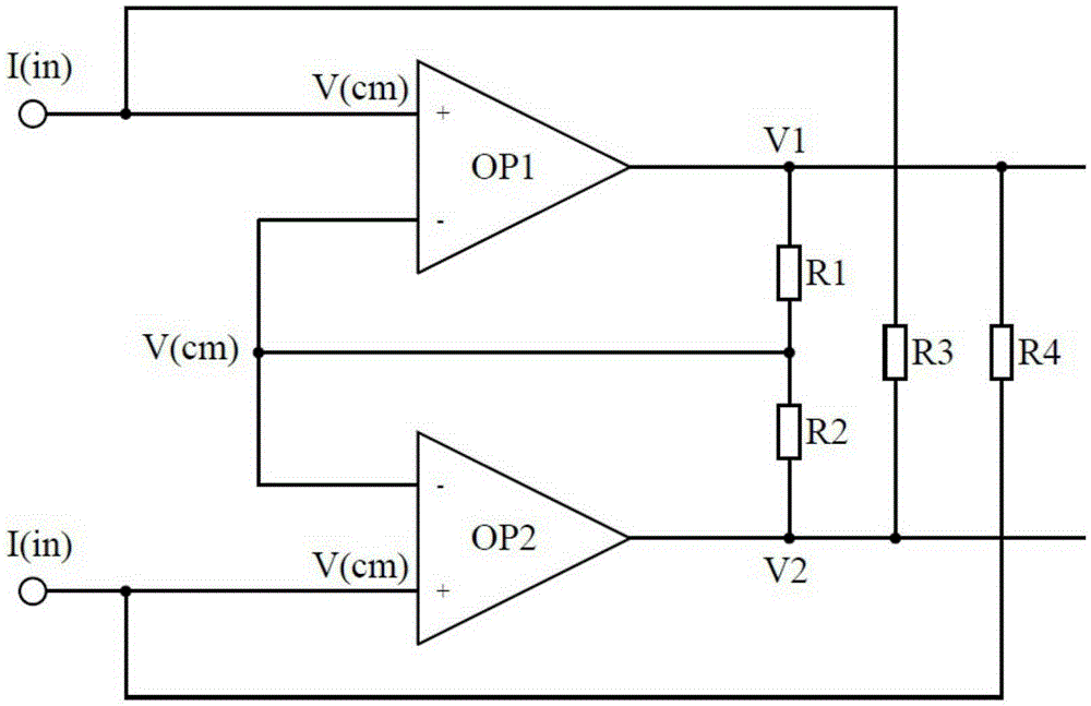
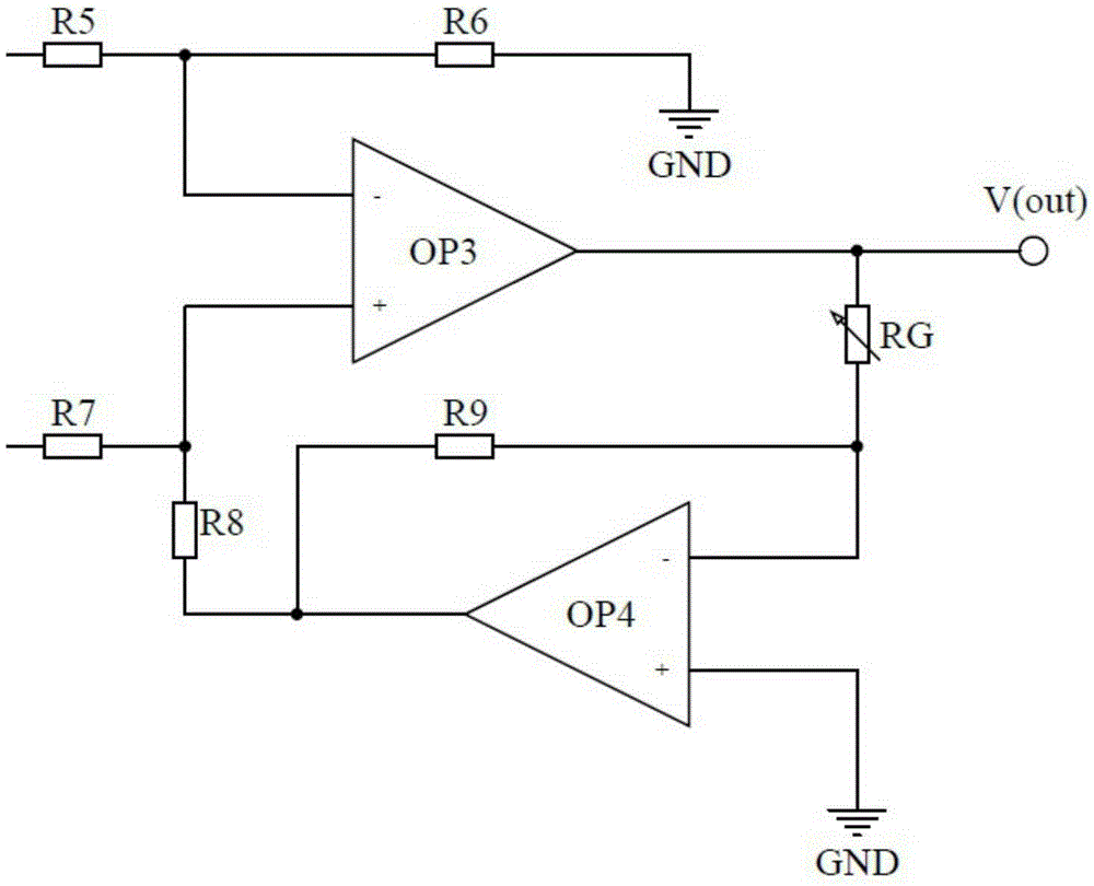
[0012] figure 1 It is a schematic diagram of the principle of the acquisition and amplification circuit for floating weak current of the present invention. As shown in the figure, the acquisition and amplification circuit for floating weak current includes:
[0013] The first operational amplifier OP1, the second operational amplifier OP2, the third operational amplifier OP3, the fourth operational amplifier OP4, the first resistor R1, the second resistor R2, the third resistor R3, the fourth resistor R4, the fifth resistor R5, the Six resistors R6, seventh resistor R7, ninth resistor R9, and variable resistor RG, wherein the floating weak current signal as the input signal is respectively input to the positive-phase input terminal of the first operational amplifier OP1 and the positive-phase input terminal of the second operational amplifier OP2 Input end, the non-inverting input end of the first operational amplifier OP1 is connected to the first end of the third resistor R...
PUM
Abstract
The invention provides a collecting and amplifying circuit for floating weak currents. The circuit comprises a first operational amplifier, a second operational amplifier, a third operational amplifier, a fourth operational amplifier, a first resistor, a second resistor, a third resistor, a fourth resistor, a fifth resistor, a sixth resistor, a seventh resistor, a ninth resistor and a variable resistor. The first operational amplifier, the second operational amplifier, the first resistor, the second resistor, the third resistor and the fourth resistor form a collecting circuit for collecting the floating weak currents and converting the currents into voltage signals, and the third operational amplifier, the fourth operational amplifier, the fifth resistor, the sixth resistor, the seventh resistor, the ninth resistor and the variable resistor form an amplifying circuit which is used for amplifying the converted voltage signals in a linear mode. The collecting and amplifying circuit for the floating weak currents can accurately collect the signals of the floating weak currents to be measured, convert the currents into the voltage signals, and amplify the signals in the linear mode, and the sequent signals processing is facilitated.
Description
technical field [0001] The invention relates to the field of electricity, and more specifically, to an acquisition and amplification circuit for floating weak current. Background technique [0002] Floating current is generally generated inside the sensor, instrument output, etc. Usually, these floating currents are relatively weak in magnitude, so they are called floating weak currents. The circuit model for this current can be represented as a current source. In order to reflect the characteristics of the actual current signal in the model, the model of the current source is limited as follows: the value is small and variable. The current signal must be generated in a closed loop, and if its magnitude is to be measured, the current must be closed into the measurement circuit. This will cause a problem: the measurement circuit usually has a certain input impedance, and this impedance is introduced into the loop of the circuit signal under test, which will weaken the curr...
Claims
Application Information
Patent Timeline
Application Date:The date an application was filed.
Publication Date:The date a patent or application was officially published.
First Publication Date:The earliest publication date of a patent with the same application number.
Issue Date:Publication date of the patent grant document.
PCT Entry Date:The Entry date of PCT National Phase.
Estimated Expiry Date:The statutory expiry date of a patent right according to the Patent Law, and it is the longest term of protection that the patent right can achieve without the termination of the patent right due to other reasons(Term extension factor has been taken into account ).
Invalid Date:Actual expiry date is based on effective date or publication date of legal transaction data of invalid patent.