Device and method for detecting fuse mounting position of vehicle body control module

A vehicle body control module and detection device technology, which is applied in the direction of measuring devices, optical devices, and optical testing for defects/defects, can solve problems such as error-prone, unusable, and unreliable performance, and prevent interference from external vibrations. The effect of improving the environmental performance and reducing the interference of light

Inactive Publication Date: 2014-04-30
ATECH AUTOMOTIVE WUHU
View PDF7 Cites 7 Cited by
  • Summary
  • Abstract
  • Description
  • Claims
  • Application Information

AI Technical Summary

Problems solved by technology

[0002] The electronic control of the car body has many functions. The body control module that combines some or all of these functions needs to install fuses of different specifications (maybe the same size but different colors) (up to dozens of five or six types of fuses) , the fuse is very easy to be installed in the wrong position, and to judge whether these fuses are installed in the correct position, at present, it mainly depends on the human eye to compare the standard sample card to judge the correct installation position of the fuse, which is not only very inefficient but also very error-prone
Although the use of image recognition technology can solve the problem of low efficiency of manual recognition and judgment, image recognition devices are often unstable, and even cost hundreds of thousands of equipment. The performance is unreliable and the accuracy cannot be achieved only because of external vibrations, lighting and other problems. are effectively guaranteed and cannot be used on the production line in the end

Method used


Image

  • Device and method for detecting fuse mounting position of vehicle body control module
  • Device and method for detecting fuse mounting position of vehicle body control module
  • Device and method for detecting fuse mounting position of vehicle body control module

Examples


Embodiment Construction

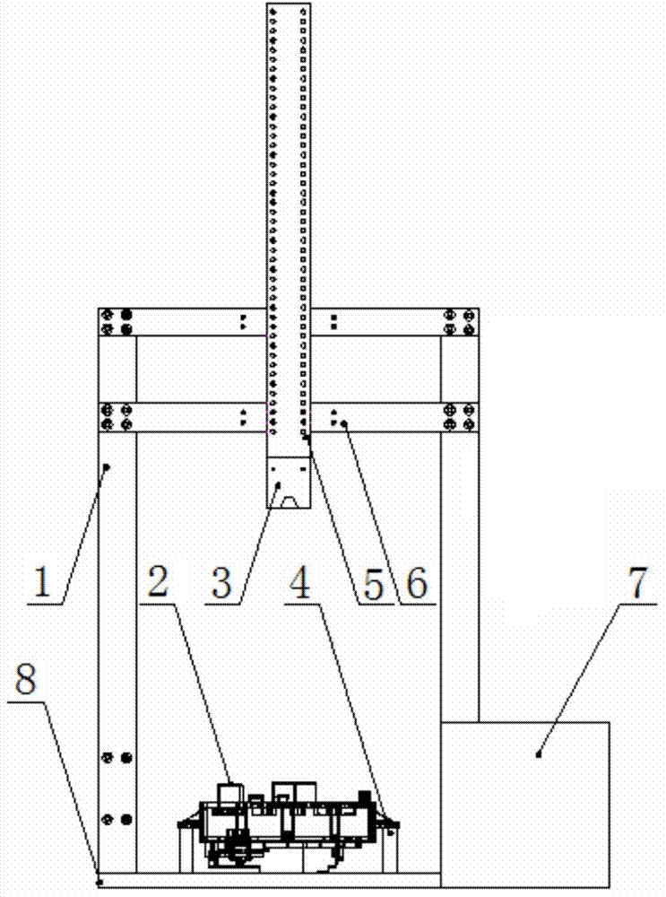
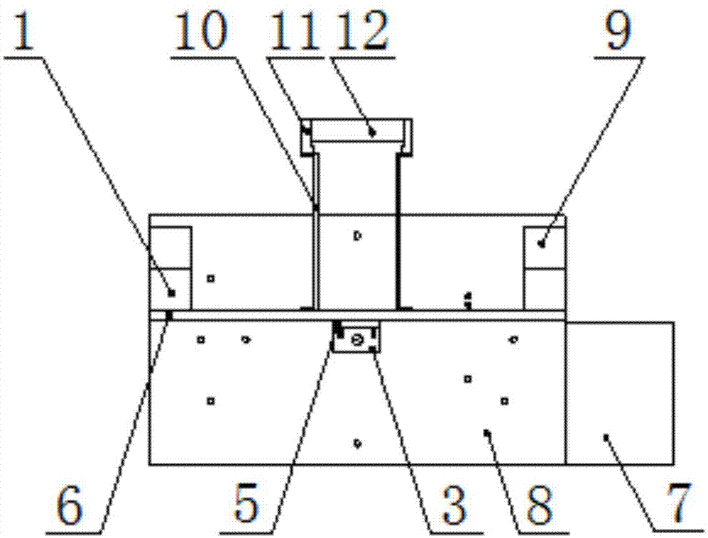
[0025] figure 1 It is a structural schematic diagram of the detection device for the installation position of the body control module fuse of the present invention, figure 2 for figure 1 A top view of the structure shown, image 3 It is a schematic structural diagram of the LED light source adjustment seat in the present invention, Figure 4 for image 3 Left view of the structure shown, Figure 5 It is a structural schematic diagram of the camera fixing plate in the present invention. Depend on Figure 1-Figure 5 Combining the structures shown, it can be seen that the detection device for the installation position of the body control module fuse includes a base 8 and a pillar 1 vertically installed on the base 8, and the pillar 1 is installed at both ends of the base 8, and the two pillars 1 are provided with Cross arm 6, and the two ends of cross arm 6 are respectively installed on different pillars 1, and one side of cross arm 6 is provided with camera fixed plate 5,...


PUM


Abstract

The invention discloses a device and method for detecting a fuse mounting position of a vehicle body control module. The detecting device comprises a base and supporting columns vertically arranged on the base, the supporting columns are arranged at the two ends of the base, cross arms are arranged on the two supporting columns, the two ends of each cross beam are mounted on the different supporting columns respectively, a camera fixing plate is arranged on one sides of the cross arms, a camera is arranged on the tail portion of the camera fixing plate, and an LED light source is arranged on the other sides of the cross arms. A vehicle body control module locating column used for fixing the vehicle body control module is arranged at the position, below the camera, on the base. The detecting device further comprises a control and display box used for displaying whether the fuse mounting position is correct or not. The device for detecting the fuse mounting position of the vehicle body control module of the special structure enables the controlled vehicle body control module and the camera to be connected and fixed to be a mechanical whole through a mechanical device, the interference from outside vibration can be effectively prevented, and test reliability is improved.

Description

technical field [0001] The invention relates to the field of automotive electronics, in particular to a detection device and a detection method for the installation position of a fuse of a vehicle body control module. Background technique [0002] The electronic control of the car body has many functions. The body control module that combines some or all of these functions needs to install fuses of different specifications (maybe the same size but different colors) (up to dozens of five or six types of fuses) , The fuse is very easy to be installed in the wrong position, and to judge whether these fuses are installed in the correct position, at present, it mainly depends on the human eye to compare the standard sample card to judge the correct installation position of the fuse, which is not only inefficient but also very error-prone. Although the use of image recognition technology can solve the problem of low efficiency of manual recognition and judgment, image recognition ...

Claims


Application Information

Patent Timeline
IPC IPC(8): G01B11/00G01N21/88
Inventor 陈泽坚
Owner ATECH AUTOMOTIVE WUHU
Why Eureka
Try Eureka