Crankshaft connecting rod assembly

A crankshaft connecting rod and assembly technology, which is applied in the direction of engine components, machine/engine, engine lubrication, etc., can solve the problems of increased wear of needle roller bearings, seizure, and affecting the service life of the crankshaft connecting rod assembly, etc., to achieve processing Simple manufacture, less oil pollution, good practical effect

Active Publication Date: 2014-04-30
JIANGSU GANGYANG
View PDF5 Cites 3 Cited by
  • Summary
  • Abstract
  • Description
  • Claims
  • Application Information

AI Technical Summary

Problems solved by technology

The disadvantage of the prior art is that there are inevitably impurities in the lubricating oil. After long-term use, the oil will accumulate on the needle bearings, which will lead to increased wear and even seizure of the needle bearings, seriously affecting the crankshaft and connecting rod assembly. service life

Method used


Image

  • Crankshaft connecting rod assembly

Examples


Embodiment Construction

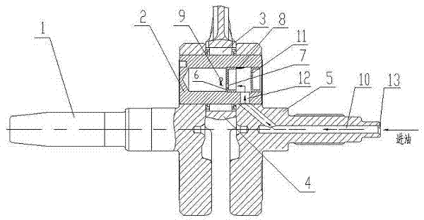
[0017] Referring to accompanying drawing 1, the crankshaft connecting rod assembly shown in the embodiment of the present invention includes a left crank 1, a right crank 5 and a connecting rod 4, the connecting rod 4 is located between the left crank 1 and the right crank 5, and passes through the crank The pin 2 is connected with the left crank 1 and the right crank 5; a needle bearing 3 is arranged between the crank pin and the connecting rod; there is a cavity in the crank pin 2, and an oil plug 11 is installed on one side of the cavity, and there is an oil plug 11 in the right crank. The oil channel 10 of the above-mentioned cavity is connected through the inclined oil hole 12, and the above-mentioned cavity is also opened with a small oil hole 9 connected to the needle bearing 3. It is characterized in that it also includes an oil separator 6 installed in the above-mentioned cavity. , the oil separation part is a bowl with a separation oil hole 7 at the bottom, which is i...


PUM


Abstract

The invention relates to a crankshaft connecting rod assembly which comprises a left crank, a right crank and a connecting rod. The connecting rod is positioned between the left crank and the right crank and is connected with the left crank and the right crank by a crankpin; a needle roller bearing is arranged between the crankpin and the connecting rod; a cavity is arranged in the crankpin, an oil plug is arranged on one side of the cavity, the right crank is communicated with an oil channel of the cavity via an inclined oil hole formed in the right crank, and a small oil hole which is communicated with the needle roller bearing is further formed in the cavity. The crankshaft connecting rod assembly is characterized by further comprising an oil stain separating part, the oil stain separating part is mounted in the cavity and is a bowl-shaped part, a separating oil hole is formed in the bottom of the bowl-shaped part, and the bowl-shaped part is mounted between the small oil hole and the inclined oil hole. The crankshaft connecting rod assembly has the advantages that lubricating oil is retained when flowing through the oil stain separating part, oil stain with high specific gravity can be thrown to side walls of the cavity under the effect of centrifugal force, the side walls of the cavity are far away from a rotating center, accordingly, oil stain which flows into the needle roller bearing can be greatly reduced, and the needle roller bearing cannot be easily abraded; the crankshaft connecting rod assembly is simple in machining and manufacturing, and a good service effect can be realized.

Description

technical field [0001] The invention relates to the field of mechanical technology, in particular to a crankshaft connecting rod assembly. Background technique [0002] The crankshaft and connecting rod assembly is an important moving part for the engine to realize the working cycle and complete the energy conversion. In the prior art, the crankshaft connecting rod assembly includes a left crank, a right crank and a connecting rod, and the connecting rod is located between the left crank and the right crank, and is connected with the left crank and the right crank through a crank pin; There is a needle bearing between the connecting rods; there is a cavity in the crank pin, and an oil plug is installed on one side of the cavity, and there is an oil passage in the right crank that communicates with the above cavity through an oblique oil hole, and the above cavity is also opened with a connecting roller. Small oil hole at the needle bearing. The lubricating oil enters the c...

Claims


Application Information

Patent Timeline
IPC IPC(8): F01M1/10F01M1/06
Inventor 唐小军丁小军孙健李加栋
Owner JIANGSU GANGYANG
Why Eureka
Try Eureka