
Adhesive tape machine speed detection method and device

A speed detection and belt conveyor technology, which is applied to conveyor control devices, conveyor objects, transportation and packaging, etc., can solve the problems of installation and debugging trouble, damage, easy wear, etc., and achieves convenient debugging and simple threshold setting. Effect

Inactive Publication Date: 2014-04-30
PANGANG GRP XICHANG STEEL & VANADIUM CO LTD
View PDF6 Cites 2 Cited by
  • Summary
  • Abstract
  • Description
  • Claims
  • Application Information

AI Technical Summary

Problems solved by technology

By monitoring the speed of the tape machine, you can know the fault status of the tape machine in a timely manner such as slipping, overspeeding, and tearing. At present, there are many slipping and tearing monitoring devices, but they are generally troublesome to install and debug, and are easy to wear and tear. Disadvantages such as damage due to impact

Method used


Image

  • Adhesive tape machine speed detection method and device
  • Adhesive tape machine speed detection method and device

Examples


Embodiment Construction

[0015] Hereinafter, embodiments of the present invention will be described in detail with reference to the drawings.

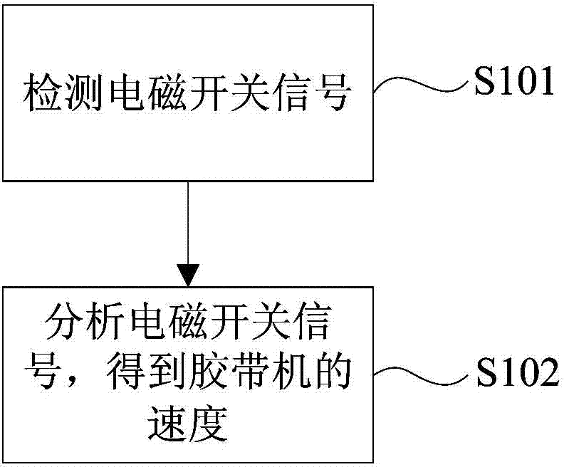
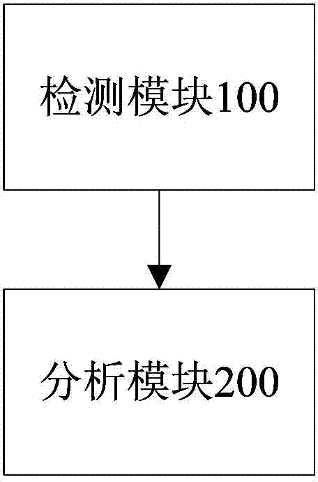
[0016] In general, the speed detection method for tape machine according to the present invention includes the following steps: detecting the electromagnetic switch signal, wherein the electromagnetic switch signal is the proximity body welded on the tail bracket of the tape machine and the electromagnetic proximity switch on the tail drum of the tape machine The signal generated by contact during one revolution; the electromagnetic switch signal is analyzed to obtain the speed of the tape machine.

[0017] The method for detecting the speed of a tape machine of the present invention will be described in detail below in conjunction with specific embodiments of the present invention.

[0018] figure 1 is a flowchart of a speed detection method for a tape machine according to an exemplary embodiment of the present invention.

[0019] In step S101, the electrom...


PUM


Abstract

The invention provides an adhesive tape machine speed detection method and device. The adhesive tape machine speed detection method comprises detecting electromagnetic switch signals which are generated due to contact between an electromagnetic proximity switch which is arranged on a tail portion rolling support of an adhesive tape machine and a proximity body which is welded to a tail portion rolling drum of an adhesive tape machine during the process of rotating for one circle; analyzing the electromagnetic switch signals and obtaining the speed of the adhesive tape machine. The adhesive tape machine speed detection method has the advantages of achieving various protection of sliding, overspeed and tearing of the adhesive tape machine, being convenient to debug and simple in threshold setting and enabling the detection to be multifunctional.

Description

technical field [0001] The invention relates to a tape machine, and more specifically, to a speed detection method and device for a tape machine. Background technique [0002] At present, tape machines are widely used in various industries. Slip detection is a fault condition that must be detected by tape machines, and the speed of tape machines is also a production parameter that operators care about. By monitoring the speed of the tape machine, you can know the fault status of the tape machine in a timely manner such as slipping, overspeeding, and tearing. At present, there are many slipping and tearing monitoring devices, but they are generally troublesome to install and debug, and are easy to wear and tear. Disadvantages such as damage due to impact. [0003] Therefore, a method for detecting the speed of the tape machine that is convenient for debugging is needed. Contents of the invention [0004] The purpose of the present invention is to solve the above technical...

Claims


Application Information

Patent Timeline
Patent Type & Authority Applications(China)
IPC IPC(8): B65G43/02B65G43/04B65G43/06
Inventor 李仲斌
Owner PANGANG GRP XICHANG STEEL & VANADIUM CO LTD
Learn More