A pipe threading method for threading the steel wire of the handle of the bucket into the handle

A steel wire and handle technology, which is applied in the field of pipe penetration, can solve the problems of high product failure rate, difficulty in ensuring that the handle is located in the center of the steel wire, and low work efficiency, and achieve the effect of simple structure, low cost and high efficiency

Active Publication Date: 2015-09-09
杜丽红
View PDF5 Cites 0 Cited by
  • Summary
  • Abstract
  • Description
  • Claims
  • Application Information

AI Technical Summary

Problems solved by technology

[0002] The handle of the bucket is very common, which includes a steel wire at both ends of the bucket body for lifting the bucket body, a handle located at the steel wire handle part and sleeved on the steel wire, however, the steel wire is inserted into the handle Inside, it is basically manually operated, firstly, the work efficiency is low; secondly, after the steel wire passes through the handle, it is sent into the forming mold for molding, and it is difficult to ensure that the handle is located at the center of the steel wire (the handle is located at the handle of the steel wire), resulting in a high rate of product failure

Method used


Image

  • A pipe threading method for threading the steel wire of the handle of the bucket into the handle
  • A pipe threading method for threading the steel wire of the handle of the bucket into the handle

Examples


Embodiment Construction

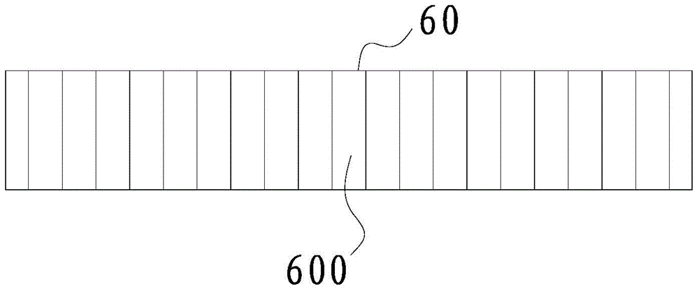
[0017] like figure 1 and figure 2 As shown, the pipe threading method for threading the steel wire of the bucket handle into the handle provided by the present embodiment, the pipe threading device adopted includes a steel wire supply unit 1 (used to organize the steel wires and output them one by one, the technical field It is easy for people to think of it, so it will not be described in detail here), the handle supply unit 2 (for handling the handles and can be output one by one, it is easy for those skilled in the art to think of it, so it will not be described in detail here), and it is used to transfer the steel wire 10 and the handle The conveyer belt 3 of 20 and the first driving mechanism that drives the conveyer belt 3 to rotate are arranged on the conveyer belt 3 for respectively synchronizing the steel wire 10 located in the steel wire supply unit 1 and the handle 20 located in the handle supply unit 2 The hooked first hook 5 and the second hook 4, and the insert...


PUM


Abstract

The invention discloses a pipe penetration method for enabling steel wires of bucket handles to penetrate the handles. The device comprises a steel wire supply unit, a handle supply unit, a conveying belt, a first driving mechanism, a first hook and a second hook which are arranged on the conveying belt and used for synchronously hooking the steel wires arranged in the steel wire supply unit and the handles located in the handle supply unit synchronously and a crossing unit used for enabling the steel wires in the first hook to penetrate the handles in the second hook. Axes of the steel wires and the handles on the first hook and the second hook are located on the same straight line. The crossing unit comprises an inclined belt arranged in the conveying direction of the conveying belt and a second driving mechanism. The inclined belt inclines towards the inside of the conveying belt in the conveying direction of the conveying belt, one end of each steel wire can abut against the inclined belt. When the handles are located in the middles of the steel wires, the steel wires deviate from the inclined belt. By means of the method, the steel wires can penetrate the handles automatically, and each handle is located at the middle of a corresponding steel wire.

Description

technical field [0001] The invention relates to a pipe threading method for threading a steel wire of a pail handle into the handle. Background technique [0002] The handle of the bucket is very common, which includes a steel wire at both ends of the bucket body for lifting the bucket body, a handle located at the steel wire handle part and sleeved on the steel wire, however, the steel wire is inserted into the handle Inside, it is basically manually operated. Firstly, the work efficiency is low; secondly, after the steel wire passes through the handle, it is sent into the forming mold for molding. It is difficult to ensure that the handle is located at the center of the steel wire (the handle is located at the steel wire handle), As a result, the product failure rate is higher. Contents of the invention [0003] The technical problem to be solved by the present invention is to overcome the deficiencies of the prior art and provide a pipe threading method for threading t...

Claims


Application Information

Patent Timeline
Patent Type & Authority Patents(China)
IPC IPC(8): B21F15/00
Inventor 沈建洪
Owner 杜丽红
Why Eureka
Try Eureka