Wedge-lock-type bidirectional locking mechanism of pull tower

A technology of locking mechanism and wedge lock, which is applied in the field of pulling tower locking mechanism, can solve the problems of affecting mobility, the weight of pulling tower, and increasing manufacturing cost, etc., and achieve the effect of function improvement, elimination of easy movement, and excellent maneuverability

Inactive Publication Date: 2014-04-30
烟台三重技术股份有限公司
View PDF8 Cites 2 Cited by
  • Summary
  • Abstract
  • Description
  • Claims
  • Application Information

AI Technical Summary

Problems solved by technology

The disadvantage is that the structure is complex and the process is cumbersome; also because the puller is heavy, it often requires a large locking force, the gap between the puller and the platform is difficult to eliminate, and false locks often occur, and often cause early wear and tear of the thread pair. Deformation of the mechanism; especially when the tower is stretched vigorously, it is easy to move or tilt, resulting in locking failure
The second is to use a special locking cylinder to drive the lock head to lock. Although this mechanism has a better locking effect, it increases the manufacturing cost on the one hand, and on the other hand affects the mobility of its rotation due to the increase in the self-weight of the equipment. ; In addition, only relying on the lock head to implement locking, there is still a hidden danger of failure caused by movement

Method used


Image

  • Wedge-lock-type bidirectional locking mechanism of pull tower
  • Wedge-lock-type bidirectional locking mechanism of pull tower
  • Wedge-lock-type bidirectional locking mechanism of pull tower

Examples


Embodiment Construction

[0028] The present invention will be further described below in conjunction with the accompanying drawings and specific embodiments.

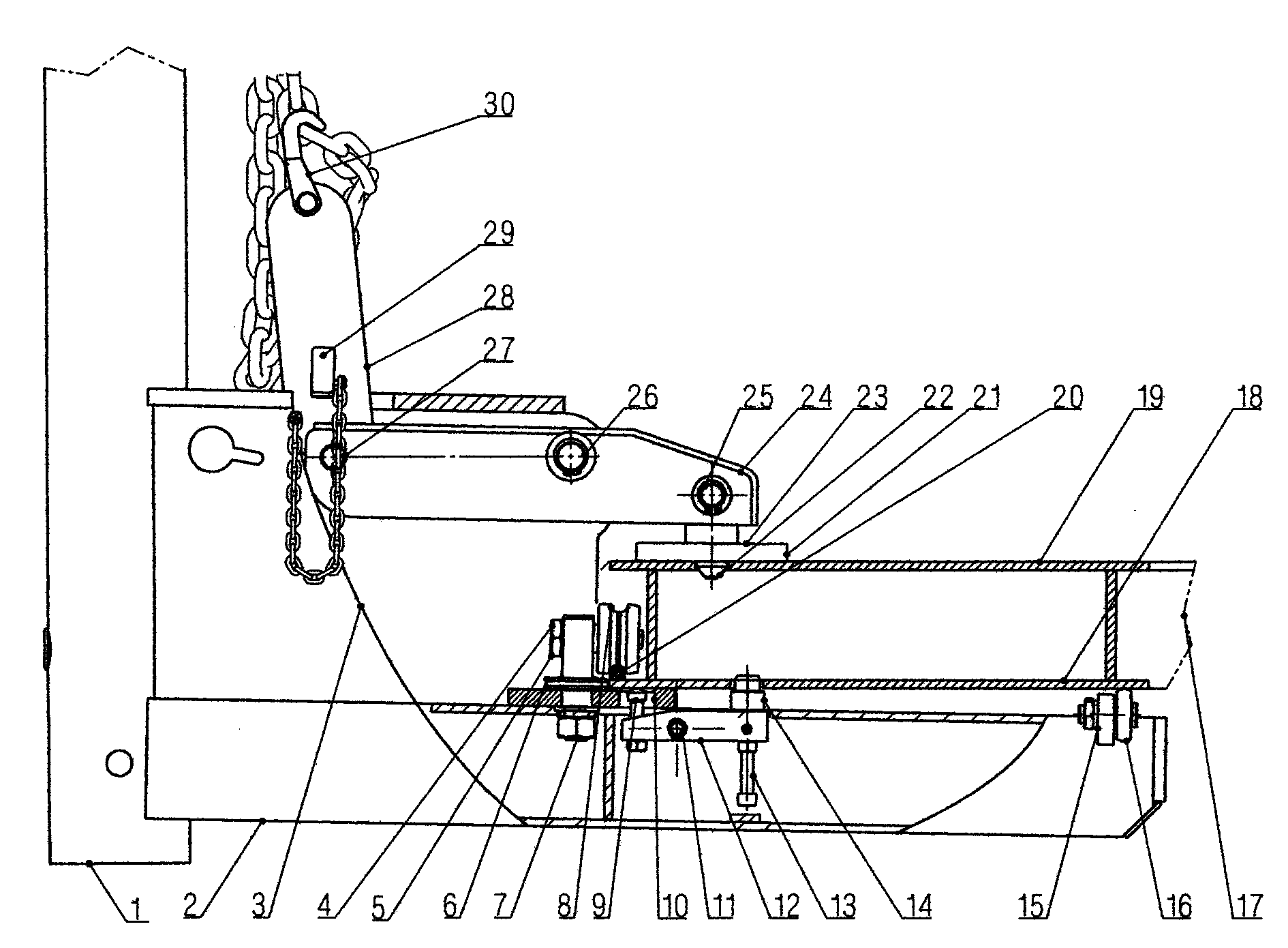
[0029] like figure 1 , the embodiment of the present invention includes the tower arm 2 and the tower column 1 of the tower, and the upper frame 3 is fixedly installed in the inner corner area of ​​the tower arm 2 and the tower column 1 .

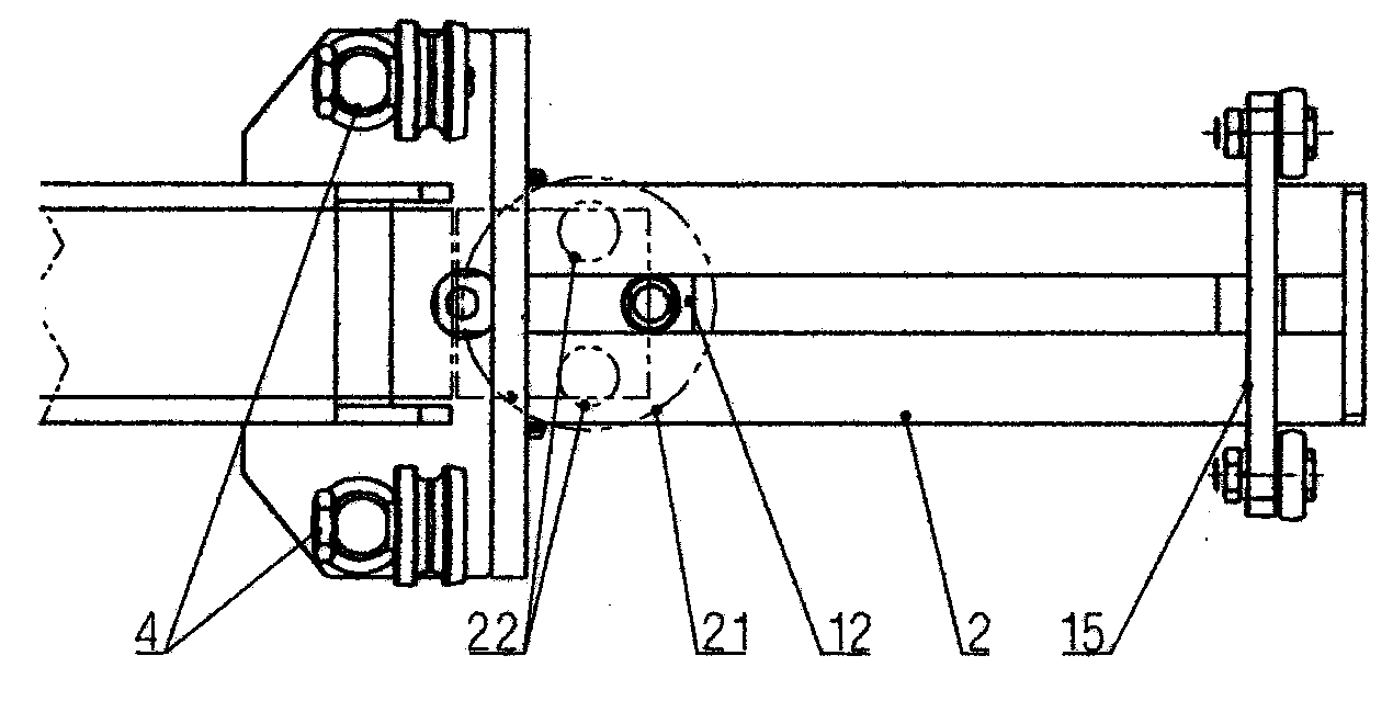
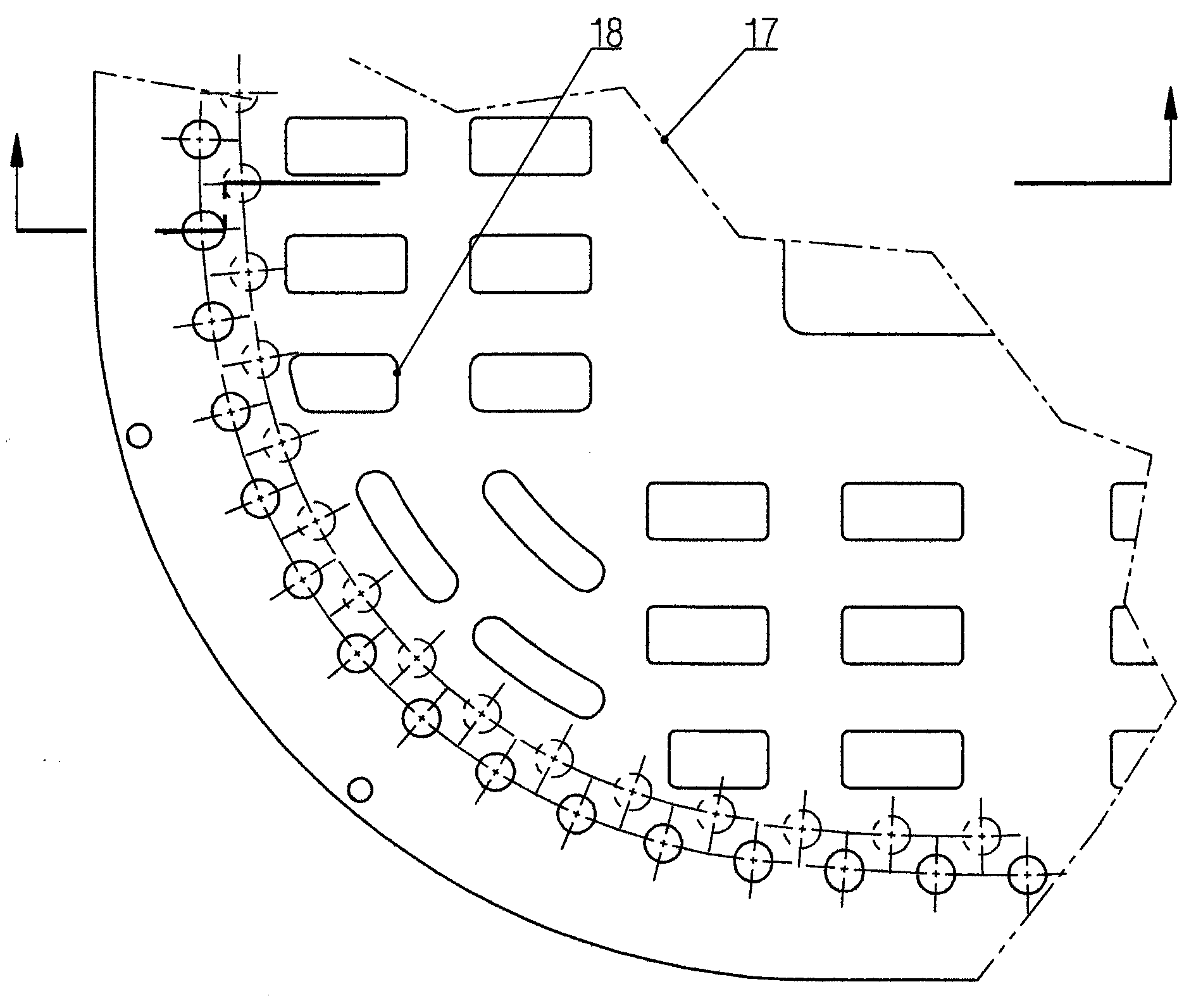
[0030] like figure 1 , figure 2 and Figure six , also includes the lower arm 12 arranged in the notch set on the top surface of the tower arm 2, located in front of the upper frame 3 and connected to the tower arm 2 through the first hinge shaft 11, the first hinge shaft 11 is located on the lower arm 12 back position. The top of the front end of the lower arm 12 is equipped with a touch pin 14 , and the top of the tail end of the lower arm 12 is equipped with a ball screw 9 . A limit screw 13 located at the lower end of the touch pin 14 is also installed on the lower arm 12 .

[0031] still as figu...


PUM


Abstract

The invention discloses a wedge-lock-type bidirectional locking mechanism of a pull tower. The wedge-lock-type bidirectional locking mechanism comprises a lower arm connected on a tower arm through a hinging shaft and an upper arm connected with an upper frame through a hinging shaft in the middle, a collision pin used for being wedged in a baseplate locking hole of a platform during locking is mounted at the top of one end of the lower arm, an upper lock head is connected at the front end of the upper arm through a hinging shaft and provided with a cone head used for being buckled in a lock hole of the platform, the lower end, longitudinally penetrating a notch arranged on the top face of the upper frame, of a wedge hole lock plate is connected with the rear end of the upper arm through a fourth hinging shaft, a chain grapnel used for being in suspended connection with a stretching chain is hinged to the upper end of the wedge hole lock plate, the wedge hole lock plate is provided with a wedge hole, and a wedge block is mounted in the wedge hole in a locked state and saddles on wall plates on two sides of the upper frame. The pull tower is enabled to closely cling to a lock face of the platform with the help of thrust of a stretching oil cylinder of the pull tower, the pull tower is locked on the platform through up-down meshing of double pins arranged at the top and the collision pin arranged at the bottom, and the locking state is maintained by means of manual wedge lock.

Description

[0001] technical field [0002] The invention relates to a pull tower locking mechanism of an automobile body correction machine. Background technique [0003] The pull tower is one of the main components of the car body correction machine. It is installed on the correction machine platform and is used to repair the deformed parts of the car body. Therefore, the pull tower must be able to be firmly locked on the correct position of the calibration platform, in order to apply a large pulling force to the repair target to achieve the purpose of calibration. [0004] The pull tower locking mechanism in the prior art can be roughly divided into two categories: one is manual locking. With this mechanism, when the repair vehicle drives on the correction platform, the appropriate pull tower pulling direction and locking position are first determined according to the damaged part of the car body. , and then turn the pull tower to the corresponding position along the periphery of th...

Claims


Application Information

Patent Timeline
IPC IPC(8): B21D1/12
Inventor 李宏张令浩崔建平
Owner 烟台三重技术股份有限公司
Why Eureka
Try Eureka