
Dual-rod linkage type tea leaf carding machine

A technology of tea stripping machine and double-rod linkage, which is applied in the direction of tea treatment before extraction, which can solve the problems of high energy consumption, tea leaf turning, unfavorable assembly line operation, etc., and achieve the effect of uniform heating, tight and straight stretching

Active Publication Date: 2014-04-30
HUANGSHAN QIMEN COUNTY QITA TEA MACHINERY
View PDF6 Cites 13 Cited by
  • Summary
  • Abstract
  • Description
  • Claims
  • Application Information

AI Technical Summary

Problems solved by technology

Due to various reasons, the existing tea stripping equipment in China has limited the improvement of tea strip processing technology
First of all, the existing slivers mainly use oil groove slide rails or bearing guide rails to drive the movement of the trough; At high speed, there may also be a certain amount of overturning, but the range is very small. Such a trajectory is not enough to make the tea leaves fully overturned, and under the action of a certain force, the ropes will be straightened, which will not achieve the ideal effect of tea leaves.
Secondly, most of the existing stripping equipment uses coal, gas, or electricity (resistance wire) as the heat source of the stripping machine, which consumes a lot of energy and cannot guarantee the uniformity and stability of the stripping temperature.
Most of the existing rafting machines use manual flipping and discharging, which consumes manpower
Finally, the existing rafting machines are mainly controlled manually and semi-automatically, the processing efficiency is not high, and it is not conducive to the realization of mass production assembly line operation

Method used


Image

  • Dual-rod linkage type tea leaf carding machine
  • Dual-rod linkage type tea leaf carding machine

Examples


Embodiment Construction

[0016] In order to make the object, technical solution and advantages of the present invention clearer, the present invention will be further described in detail below in conjunction with the accompanying drawings and embodiments. It should be understood that the specific embodiments described here are only used to explain the present invention, not to limit the present invention.

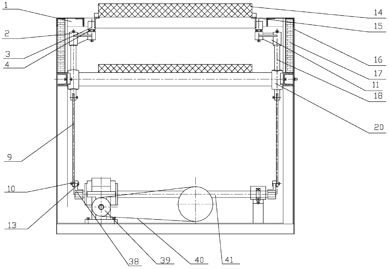
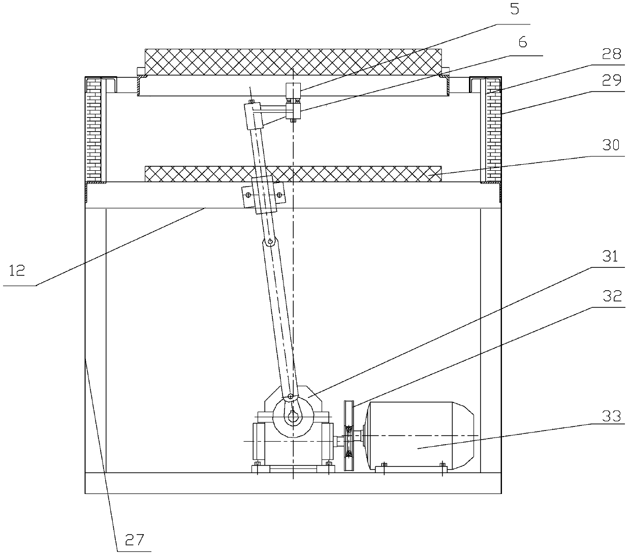
[0017] see figure 1 and figure 2 , figure 1 It is a front view of the structure of the double-rod linkage type tea slitting machine of the present invention, figure 2 for side view. A double-rod interlocking type tea slitting machine, including a frame 1, a motor 33, a transmission mechanism, a crank linkage mechanism fixed on both sides of the output shaft 41 of the transmission mechanism, and a screen groove fixed on the top of the crank linkage mechanism Pot 14, and the heating plate 13 that is positioned at screen mesh pan 14 below.

[0018] The motor 33 drives the transmission mechanism...


PUM


Abstract

The invention discloses a dual-rod linkage type tea leaf carding machine which comprises a machine frame, a motor, a transmission mechanism, crankshaft and connecting rod mechanisms fixed on the two sides of an output shaft of the transmission mechanism, sieve groove pots fixed at the top ends of the crankshaft and connecting rod mechanisms, and heating plates arranged below the sieve groove pots, wherein the motor, the transmission mechanism, the crankshaft and connecting rod mechanisms, the sieve groove pots and the heating plates are all arranged in the machine frame; the motor is used for driving the transmission mechanism to run; the output shaft of the transmission mechanism are fixedly connected with the cranks of the crankshaft and connecting rod mechanisms. According to the dual-rod linkage type tea leaf carding machine, the sieve groove pots are driven by the crankshaft and connecting rod mechanisms symmetrically arranged at the two ends of the output shaft to make an up-down reciprocating movement and a planar left-right swinging movement for carding tea leaves, and the manual sieving operation is simulated, so that the tea leaves cannot be longitudinally restricted in the sieve groove pots, and tea strips are tighter, straighter and more stretched; due to the adoption of the sieve groove pots, the tea leaves are uniformly heated and the moisture can be timely dissipated.

Description

technical field [0001] The invention relates to a tea slitting machine, in particular to a double-rod interlocking tea slitting machine. Background technique [0002] At present, with the rapid development of the modern tea beverage industry, the competition in the tea processing industry has become increasingly fierce. Improving product quality, reducing energy consumption, reducing costs, and improving efficiency have become urgent needs for tea processing enterprises. In the process of stripping, the main factors that determine the quality of tea are the movement mode and heating temperature of tea in the stripping tank (ie, the temperature of the tank body). The domestic existing bar equipment has limited the improvement of tea bar processing technology due to various reasons. First of all, the existing slivers mainly use oil groove slide rails or bearing guide rails to drive the movement of the trough; At high speed, there may also be a certain amount of overturning, ...

Claims


Application Information

Patent Timeline
IPC IPC(8): A23F3/06
Inventor 周文炳王健姜礼春
Owner HUANGSHAN QIMEN COUNTY QITA TEA MACHINERY
Learn More