
Drillship having block for preventing vortex with concave type flow stabilizer part in moonpool

A technology for stabilizing parts and drilling ships, applied in the direction of hydrodynamic characteristics/hydrostatic characteristics, hull, hull parts, etc., can solve the problems of reducing pressure variability, not reducing external flow, increasing the weight of drilling ships, etc., to achieve improvement Effects of resistance performance, improved economy, and high expectation of use value

Active Publication Date: 2014-04-23
HYUNDAI HEAVY IND CO LTD
View PDF9 Cites 4 Cited by
  • Summary
  • Abstract
  • Description
  • Claims
  • Application Information

AI Technical Summary

Problems solved by technology

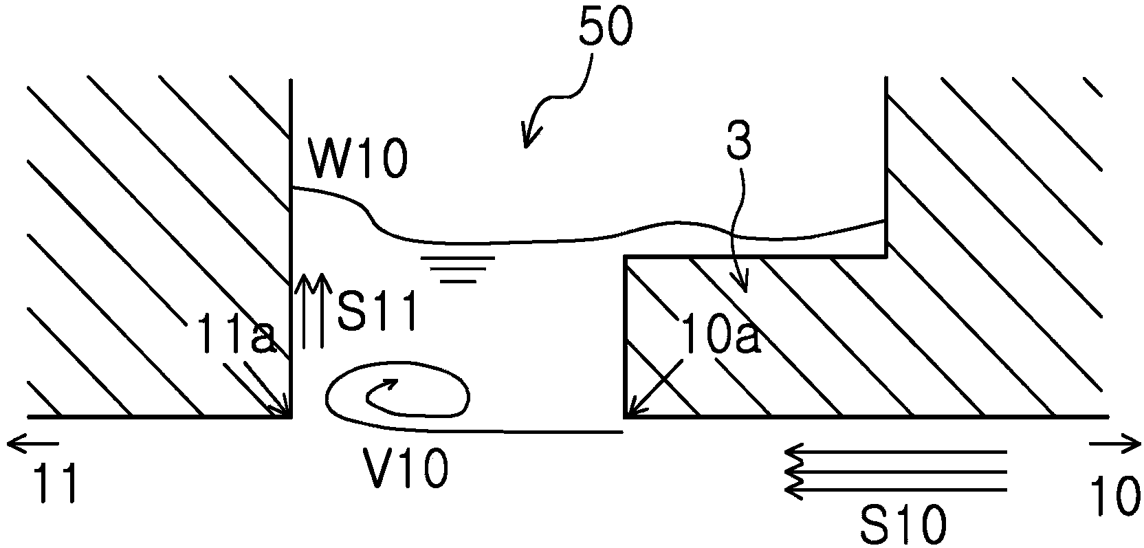
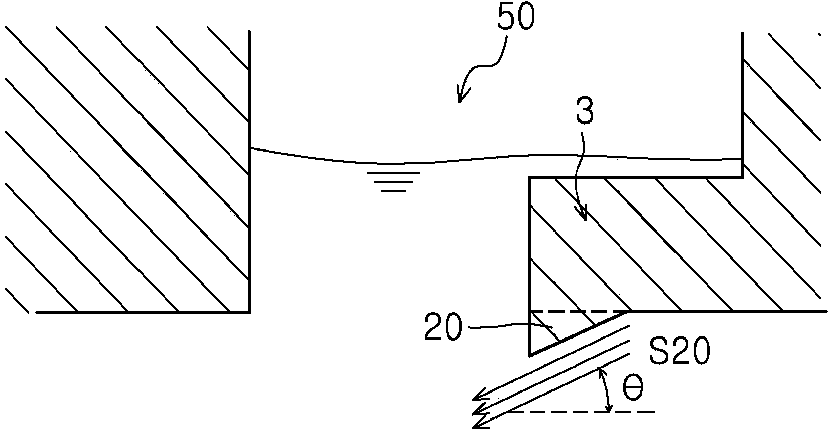
[0009] However, the flow disturbance reducing structure similar to that described has the following problems: the inclined protrusion 20 additionally formed on the bow corner and the block 3 for suppressing the vortex protrudes below the bottom surface of the sea bottom of the drilling ship, Therefore, when drying the ship, it is restricted by the water depth; in addition, when performance improvement is required while maintaining a certain peeling angle, the inclined protrusion 20 becomes too large; in addition, performance is required while maintaining the height of the inclined protrusion 20 When improving, the stripping angle is increased, so that the average resistance acting on the drilling ship increases
[0012] However, said device also has the disadvantage that it does not reduce the external flow into the interior of the well, thereby controlling the flow and vortices (Vortex) stripped from the bow corner and reducing the flow through the streamline (Streamline) at the stern corner. ) and vortex (Vortex) have little ability to fluctuate pressure; in addition, due to the setting of the overly complicated structure of the boat well, the weight and unit price increase
[0015] However, said technique also has the following disadvantages: it does not reduce the external flow into the interior of the well, so that after controlling the flow and vortex (Vortex) stripped from the bow corner, the flow line passing through the stern corner (Streamline) and vortex (Vortex) collisions are not very capable of reducing pressure fluctuations
[0016] In addition, the technology has the problem of increasing the weight of the drilling ship and increasing its manufacturing unit price due to the seawater flow transformation structure having an excessively complicated structure, which is elongated horizontally along the vertical wall to set
[0017] In addition, as technologies for suppressing the flow in a ship well, there are Korean Utility Model Registration Application No. 20-2006-24344 (Flow Suppression Structure of Ship Well), Korean Patent Application No. 10-2007-124862 (Structure of Ship Well Structure of Drilling Ship) flow reducing structure), etc., but most of them are about the structure with additional devices inside the boat well, which has the disadvantage of not reducing the flow into the inside of the boat well. Ability to reduce pressure variability caused by streamline (Streamline) and vortex (Vortex) impact at the stern corner after partially external flow to control the flow and vortex (Vortex) stripped from the bow corner It is not very large, and because of the complicated device structure added to the ship well, there are problems of increasing the weight and the manufacturing unit price of the drilling ship

Method used


Image

  • Drillship having block for preventing vortex with concave type flow stabilizer part in moonpool
  • Drillship having block for preventing vortex with concave type flow stabilizer part in moonpool
  • Drillship having block for preventing vortex with concave type flow stabilizer part in moonpool

Examples


Embodiment Construction

[0056] Hereinafter, the structures and functions of the embodiments of the present invention will be described in detail in conjunction with the accompanying drawings, as follows. In describing the embodiments of the present invention, if the relevant known functions or specific descriptions about its structure are considered to interfere with the gist of the present invention, the detailed description will be omitted.

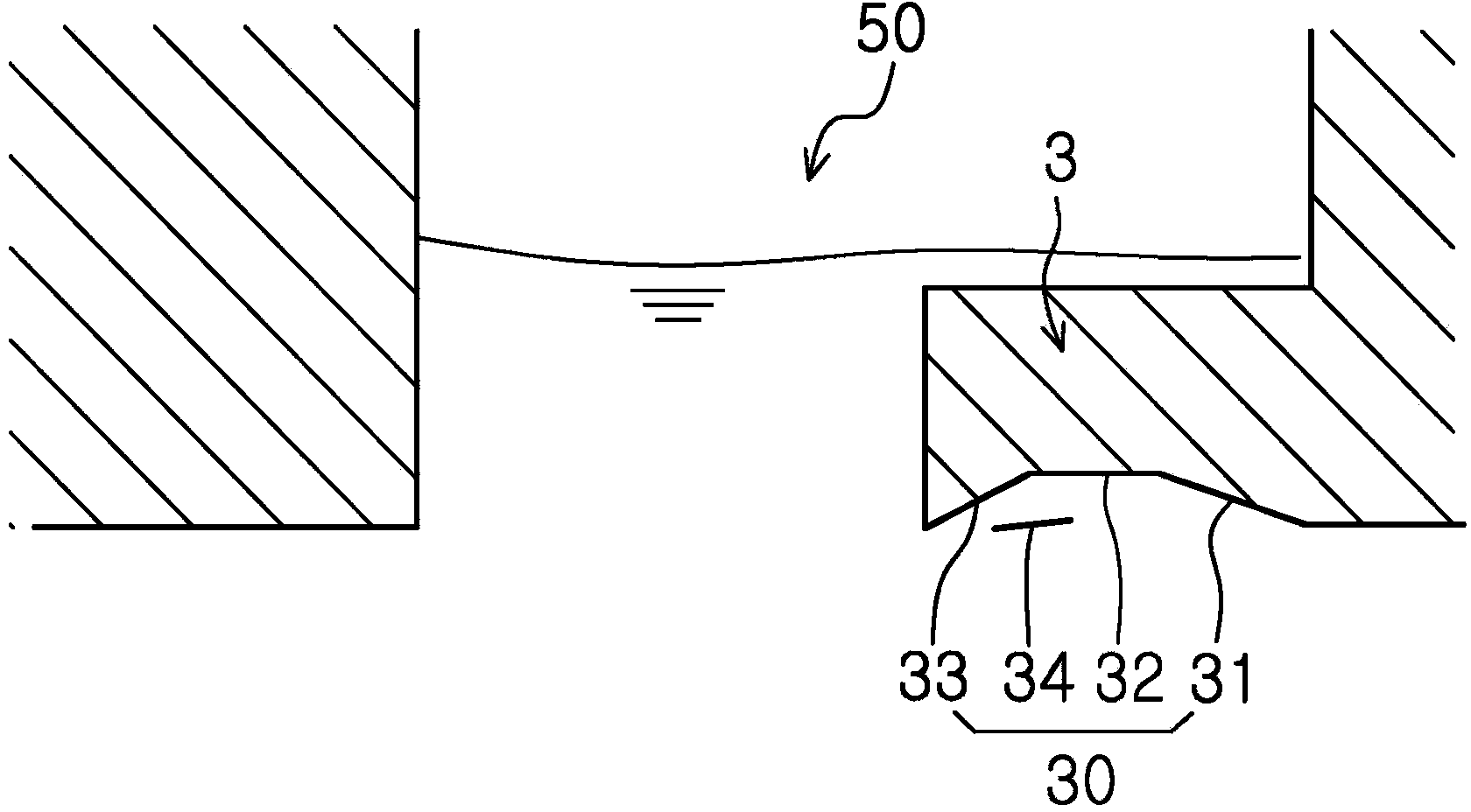
[0057] image 3 It is a side view of a boat well with a flow stabilizing part according to an embodiment of the present invention. As shown in the figure, the present invention constitutes a concave flow stabilizing part 30, which will be used to suppress the vortex generated by the external flow S10 in order to suppress The lower bottom of the block 3 of the eddy current is formed by being recessed toward the upper part of the hull, and the external flow flows into the ship well 50 vertically installed on the hull of the drilling ship. The bottom of the ship...


PUM


Abstract

The present invention relates to a drillship having a block for preventing a vortex with a concave type flow stabilizer part in a moonpool. The purpose of the present invention is to provide a drillship having a flow stabilizer part formed with a bottom surface of a block for preventing a vortex protruding from the bottom of the ship towards the stern in a moonpool to be concave toward the upper portion of the body of the ship in order to stabilize the flow in the moonpool and reduce a resistance fluctuation of the drillship. The drillship having the block for preventing the vortex in the moonpool, of the present invention, is characterized in that one position of the bottom at the lower portion of the block for preventing a vortex is processed to be concave toward the upper portion of the body of the ship so as to form a flow stabilizer part (30) such that the drillship is provided with a block for preventing a vortex formed with the concave type flow stabilizer part in the moonpool. The drillship of the present invention having the above feature can improve resistance performance of the ship and exhibit flow stabilizing effects.

Description

technical field [0001] The present invention relates to a drilling ship having a block for suppressing eddy currents formed with a concave flow stabilizing part in a ship well provided at the bottom of the ship, and more particularly to a drilling ship (Drillship) having a block for suppressing eddy currents. The shape of the bottom of the bow of the boat well suppresses the streamline and vortex (Vortex) stripped from the corners of the bow of the boat well, thereby reducing the resistance variable acting on the boat well and stabilizing the free water surface in the boat well. Concave flow stabilizing part with minimal protrusion on the bottom surface of the ship's bottom. Background technique [0002] With the development of industry and industries all over the world, the use of oil and natural gas has increased, and attention has been paid to the development of a small number of marginal oil fields or deep sea oil fields that have been neglected due to lack of economy. ...

Claims


Application Information

Patent Timeline
Patent Type & Authority Applications(China)
IPC IPC(8): B63B35/44B63B1/32
CPCB63B3/14B63B1/32B63B2003/147B63B35/44Y02T70/10
Inventor 李相奉李康勋安由原金炯宽郑锡湖郑容官权珉载
Owner HYUNDAI HEAVY IND CO LTD
Learn More