Material belt charging device of chip mounter
A technology of placement machine and feeding wheel, which is applied in the direction of assembling printed circuits, electrical components, electrical components, etc. with electrical components, can solve the problems of bulky, high cost, complex structure, etc., to simplify the mechanical structure and simplify the complexity. and precision, to achieve the effect of stable transmission
- Summary
- Abstract
- Description
- Claims
- Application Information
AI Technical Summary
Problems solved by technology
Method used
Image

Examples
no. 1 example
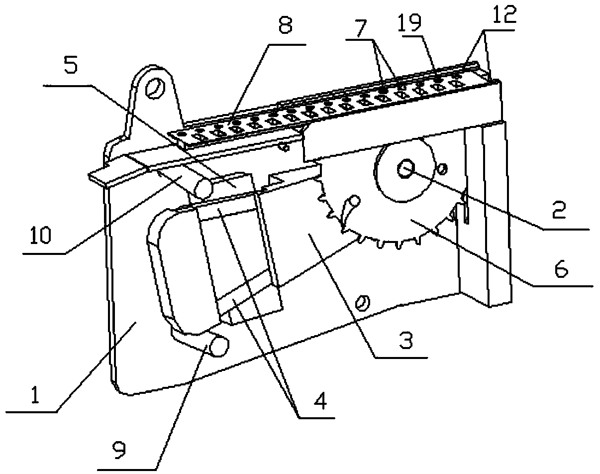
[0037] figure 1 For the first embodiment of the present invention, such as figure 1 As shown, the tape feeding device of the chip mounter provided by the present invention includes a powered oscillating voice coil motor and a feed wheel 6 driven by the oscillating voice coil motor for feeding the tape. In the present embodiment, the feed wheel 6 is a unidirectionally rotating feed ratchet; the oscillating voice coil motor includes a stator 5 that provides a magnetic field and a mover that moves relative to the stator 5, and the stator 5 is generally a permanent magnet that provides a stable magnetic field. The mover is composed of a coil support 3 and a coil 4. The coil 4 is installed on the coil support 3, and the stator 5 is fixed on the inner surface of the shell 1. The magnetic field generated when the coil 4 is energized is coupled with the magnetic field of the stator 5; The feed tooth 7 matched with the material belt hole 19, part of the feed tooth 7 passes through the...
no. 2 example
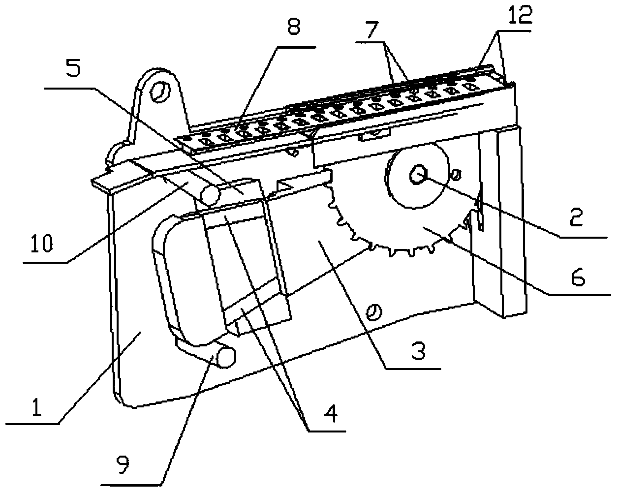
[0042] figure 2 is the second embodiment of the present invention, such as figure 2 As shown, the second embodiment is basically the same as the first embodiment, the difference is that the feed wheel in the second embodiment is a gear, and the second embodiment also includes a one-way bearing 11, one end of the coil support 3, the feed wheel The wheel 6, the one-way bearing 11, and the installation shaft 2 are coaxially installed in the casing 1, and the other end of the coil support 3 is a free end, and the swing-type voice coil motor drives the feed wheel 6 to rotate in one direction through the one-way bearing 11 to realize feeding .
no. 3 example
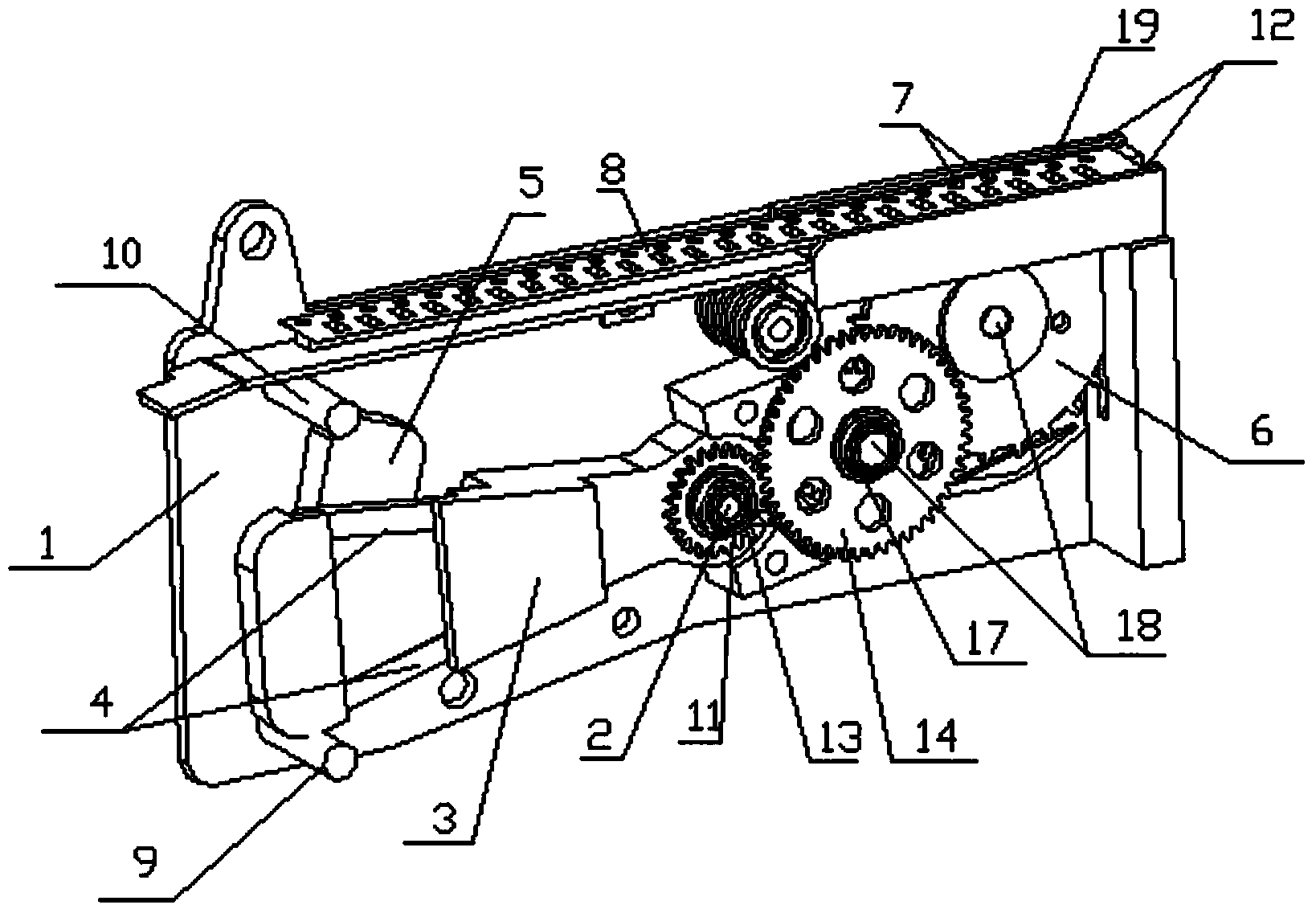
[0044] image 3 is the third embodiment of the present invention, such as image 3 As shown, the third embodiment is basically the same as the second embodiment, the difference is that the third embodiment also includes a transmission gear set, and the swing-type voice coil motor drives the feed wheel 6 to move in one direction through the transmission gear set, and the transmission The gears in the gear set are connected by the one-way bearing 11 and / or the transmission one-way bearing 17 and the transmission shaft 18. The specific connection methods can be combined arbitrarily, as long as the swing-type voice coil motor can drive the feed wheel 6 through the transmission gear set. Rotating in the opposite direction, the transmission gear set increases the torque acting on the feed wheel 6, so the output torque of the oscillating voice coil motor can be reduced, thereby reducing the volume of the motor.
[0045] Such as Figure 4 As shown, the transmission gear set includes a...
PUM
 Abstract
Description
Claims
Application Information
 - R&D
- Intellectual Property
- Life Sciences
- Materials
- Tech Scout
- Unparalleled Data Quality
- Higher Quality Content
- 60% Fewer Hallucinations
Browse by: Latest US Patents, China's latest patents, Technical Efficacy Thesaurus, Application Domain, Technology Topic, Popular Technical Reports.
© 2025 PatSnap. All rights reserved.Legal|Privacy policy|Modern Slavery Act Transparency Statement|Sitemap|About US| Contact US: help@patsnap.com