High-gain circularly-polarized antenna

A circularly polarized antenna and high gain technology, applied in the field of satellite communication, can solve the problems of large volume and low antenna gain, and achieve the effects of small volume, high gain and simple structure

Pending Publication Date: 2020-12-04
广州智讯通信系统有限公司
View PDF0 Cites 2 Cited by
  • Summary
  • Abstract
  • Description
  • Claims
  • Application Information

AI Technical Summary

Problems solved by technology

[0004] In order to overcome the deficiencies in the prior art, the object of the present invention is to provide a high-gain circularly polarized antenna, which can solve the problems of low antenna gain and large volume in the prior art maritime satellite communication system

Method used


Image

  • High-gain circularly-polarized antenna
  • High-gain circularly-polarized antenna
  • High-gain circularly-polarized antenna

Examples


Embodiment 1

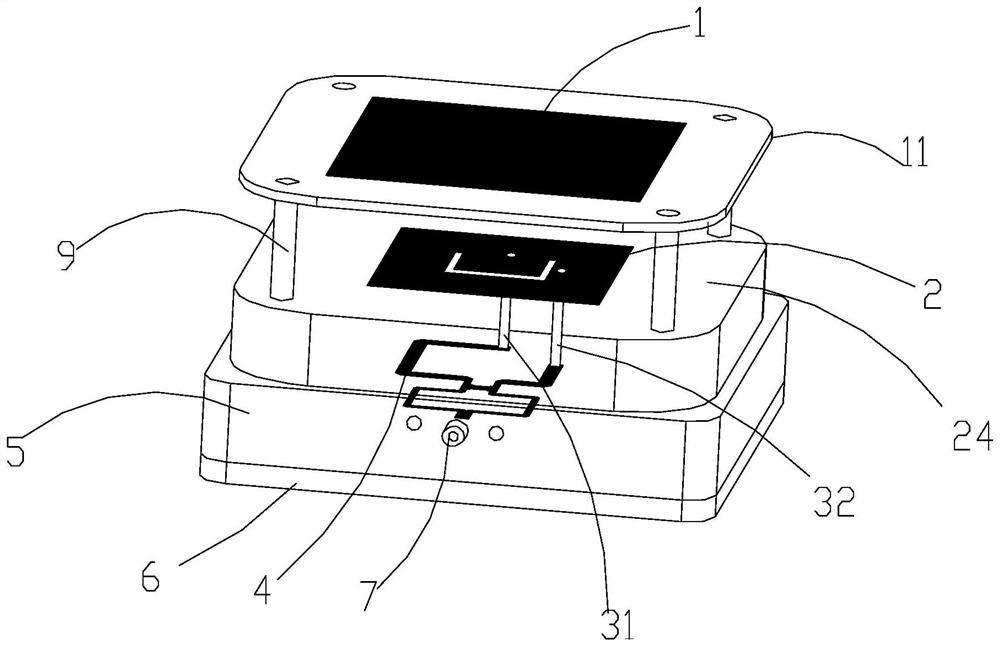
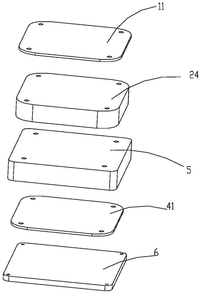
[0032] The present invention provides a preferred embodiment, such as Figure 1-5 As shown, a high-gain circularly polarized antenna includes a metal case 5 , a first dielectric substrate 24 and a second dielectric substrate 11 that are stacked sequentially from bottom to top.

[0033] The first dielectric substrate 24 is arranged on the top of the metal box body 5, and the second dielectric substrate 11 is arranged above the first dielectric substrate 24, so that the first dielectric substrate 24 is arranged between the metal box body 5 and the second dielectric substrate 11 . Preferably, an air layer is provided between the first dielectric substrate 24 and the second dielectric substrate 11 .

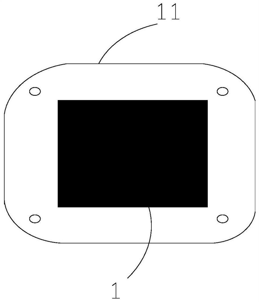
[0034] The radiation patch 2 is provided on the upper surface of the first dielectric substrate 24 , and the parasitic patch 1 is provided on the upper surface of the second dielectric substrate 11 , and the parasitic patch 1 and the radiation patch 2 are vertically opposite to each...


PUM

PropertyMeasurementUnit
thicknessaaaaaaaaaa
thicknessaaaaaaaaaa
electrical resistanceaaaaaaaaaa

Abstract

The invention discloses a high-gain circularly-polarized antenna. The high-gain circularly-polarized antenna comprises a metal box body, a first dielectric substrate and a second dielectric substratewhich are sequentially stacked from bottom to top, wherein a parasitic patch is arranged on the upper surface of the second dielectric substrate, a radiation patch is arranged on the upper surface ofthe first dielectric substrate, and the parasitic patch and the radiation patch are arranged face to face; the third dielectric substrate is arranged in the metal box body, and a Wilson power divideris arranged on the third dielectric substrate; an SMA coaxial connector is arranged on the side wall of the metal box body; a shunt port of the Wilson power divider is electrically connected with theradiation patch, and a combination port of the Wilson power divider is connected with the SMA coaxial connector to feed external equipment, so circularly-polarized wave radiation is realized; and theradiation patch is provided with a U-shaped gap. The high-gain circularly-polarized antenna provided by the invention has the characteristics of simple structure, high gain, small size and the like.

Description

technical field [0001] The invention relates to the field of satellite communication, in particular to a high-gain circularly polarized antenna. Background technique [0002] Antenna is an important component module in the maritime satellite communication system, and its performance can directly affect the performance of the entire maritime satellite communication system. At present, the antennas of maritime satellite communication systems are generally realized by circularly polarized antennas. The circularly polarized antennas are used to receive signals. On the one hand, it can reduce signal loss, and on the other hand, it can eliminate the polarization distortion caused by the Faraday rotation effect of the ionosphere. [0003] However, the antennas in the existing maritime satellite communication system have problems such as low gain and large volume, which greatly affect the system performance of the maritime satellite communication system. Contents of the invention ...

Claims


Application Information

Patent Timeline
Patent Type & Authority Applications(China)
IPC IPC(8): H01Q1/38H01Q1/50H01Q5/28H01Q5/378H01Q5/50
CPCH01Q1/38H01Q1/50H01Q5/28H01Q5/378H01Q5/50
Inventor 黄冠龙赵阁庞子裕马晓钰王世伟葛建华胡斌强何瑶袁素华朱刚
Owner 广州智讯通信系统有限公司
Why Eureka
Try Eureka