
Combined type inverter

An inverter and composite technology, which is applied in the direction of converting AC power input to DC power output, output power conversion devices, electrical components, etc. Achieve the effect of increasing inverter efficiency, reducing output harmonic content and reducing loss

Inactive Publication Date: 2014-04-23
ANHUI POWERSOLAR NEW ENERGY
View PDF8 Cites 1 Cited by
  • Summary
  • Abstract
  • Description
  • Claims
  • Application Information

AI Technical Summary

Problems solved by technology

The three-phase inverter is a high-power inverter power supply for electric power, mainly used in the military; communication; factory and enterprise uninterruptible power supply system, the ordinary three-phase inverter has a large current passing through the MOS tube, and the heat generation is relatively high. The power consumption of the tube is high, so the life of the MOS tube will be greatly shortened; and the waveform output by the ordinary three-phase inverter contains quite a lot of high-order harmonics, which will cause a great negative impact on the load, and also It will bring clutter pollution to the mains on the grid, and these inverters must be improved to improve their output waveforms

Method used


Image

  • Combined type inverter
  • Combined type inverter
  • Combined type inverter

Examples


Embodiment Construction

[0011] The present invention will be further described below in conjunction with the accompanying drawings.

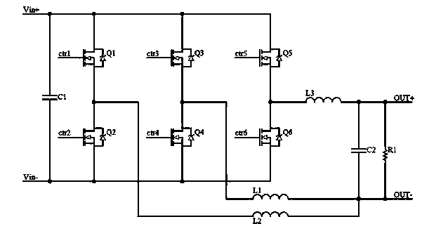
[0012] Such as figure 1 As shown, the present invention includes an input voltage, a capacitor C1 connected in parallel between the positive and negative poles of the input voltage, the positive pole of the input voltage is connected in parallel with the drains of the MOS transistor Q1, the MOS transistor Q3 and the MOS transistor Q5, and the MOS transistor The source of Q1 is connected to the drain of MOS transistor Q2, the source of MOS transistor Q3 is connected to the drain of MOS transistor Q4, the source of MOS transistor Q5 is connected to the drain of MOS transistor Q6, and the MOS transistor Q3 is connected to the drain of MOS transistor Q6. The sources of the tube Q2, the MOS tube Q4 and the MOS tube Q6 are connected to the negative pole of the input voltage;

[0013] The source of the MOS transistor Q1 and the drain of the MOS transistor Q2 are sequentially...


PUM


Abstract

The invention discloses a combined type inverter. The combined type inverter comprises input voltage, and a capacitor C1 connected between positive and negative electrodes of the input voltage in parallel, the positive electrode of the input voltage is connected with drain electrodes of an MOS tube Q1, an MOS tube Q3 and an MOS tube Q5 in parallel, a source electrode of the MOS tube Q1 is connected with a drain electrode of an MOS tube Q2, a source electrode of the MOS tube Q3 is connected with a drain electrode of an MOS tube Q4, a source electrode of the MOS tube Q5 is connected with a drain electrode of an MOS tube Q6, source electrodes of the MOS tube Q2, the MOS tube Q4 and the MOS tube Q6 are connected with the negative electrode of the input voltage; and a position between a source electrode of the MOS tube Q1 and the drain electrode of the MOS tube Q2 is connected between the source electrode of the MOS tube Q5 and the drain electrode of the MOS tube Q6 through an inductor L2, a capacitor C2 and an inductor L3 in sequence, a position between the source electrode of the MOS tube Q3 and the drain electrode of the MOS tube Q4 is connected between the source electrode of the MOS tube Q5 and the drain electrode of the MOS tube Q6 through an inductor L1, the capacitor C2 and the inductor L3 in sequence, and the capacitor C2 is connected with a load R1 in parallel.

Description

technical field [0001] The present invention relates to inverters, in particular to compound inverters. Background technique [0002] Inverter, English inverter, is a power conversion device that can convert 12V or 24V DC into 230V, 50Hz AC or other types of AC. The alternating current it outputs can be used in various equipments. It can meet the needs of users in mobile power supply places or areas without electricity to the greatest extent. The three-phase inverter is a high-power inverter power supply for electric power, mainly used in the military; communication; factory and enterprise uninterruptible power supply system, the ordinary three-phase inverter has a large current through the MOS tube, and the heat is high, and the MOS The power consumption of the tube is high, so the life of the MOS tube will be greatly shortened; and the waveform output by the ordinary three-phase inverter contains quite a lot of high-order harmonics, which will cause a great negative impac...

Claims


Application Information

Patent Timeline
Patent Type & Authority Applications(China)
IPC IPC(8): H02M7/5387H02M1/12
Inventor 陈丹平王德才杨彦辉高家富
Owner ANHUI POWERSOLAR NEW ENERGY
Learn More