A waste gas treatment equipment for nitriding furnace

A technology of waste gas treatment equipment and nitriding furnace, which is applied in the direction of incinerators, lighting and heating equipment, combustion methods, etc., can solve the problems of waste gas treatment residues in nitriding furnaces, and achieve the effect of avoiding residues

Active Publication Date: 2016-02-10
TONGFU HEAT TREATMENT KUNSHAN +1
View PDF6 Cites 1 Cited by
  • Summary
  • Abstract
  • Description
  • Claims
  • Application Information

AI Technical Summary

Problems solved by technology

[0003] In view of the above-mentioned shortcoming of the prior art, the object of the present invention is to provide a kind of waste gas treatment equipment for nitriding furnace, to solve the problem of the above-mentioned nitriding furnace waste gas treatment residue

Method used


Image

  • A waste gas treatment equipment for nitriding furnace
  • A waste gas treatment equipment for nitriding furnace
  • A waste gas treatment equipment for nitriding furnace

Examples


Embodiment Construction

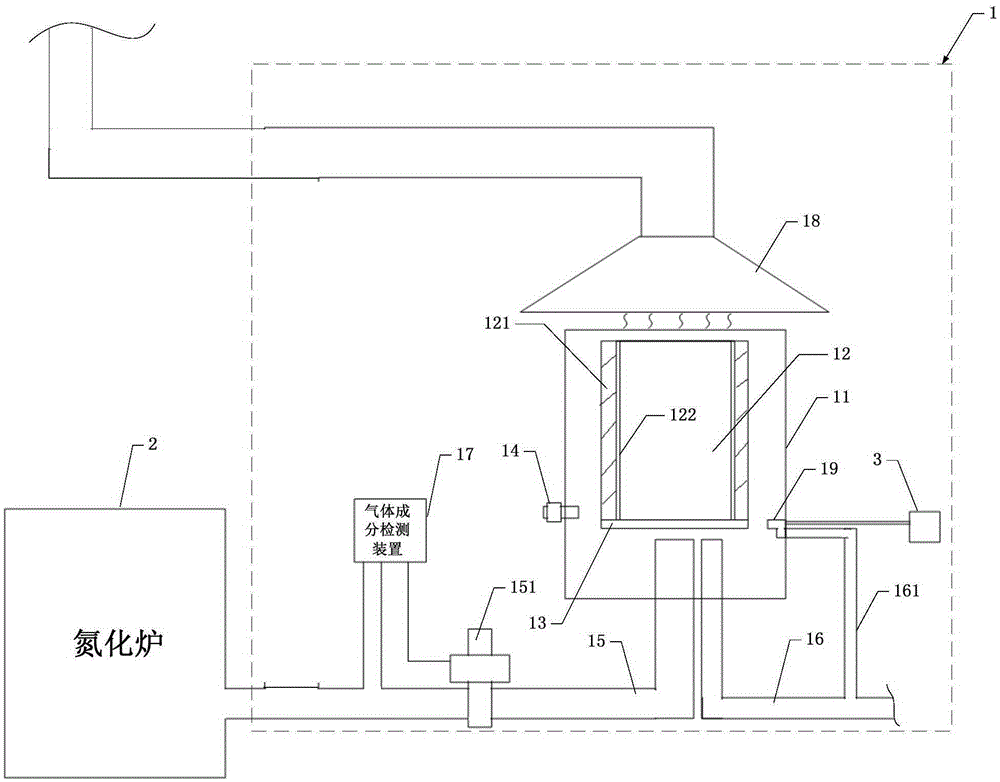
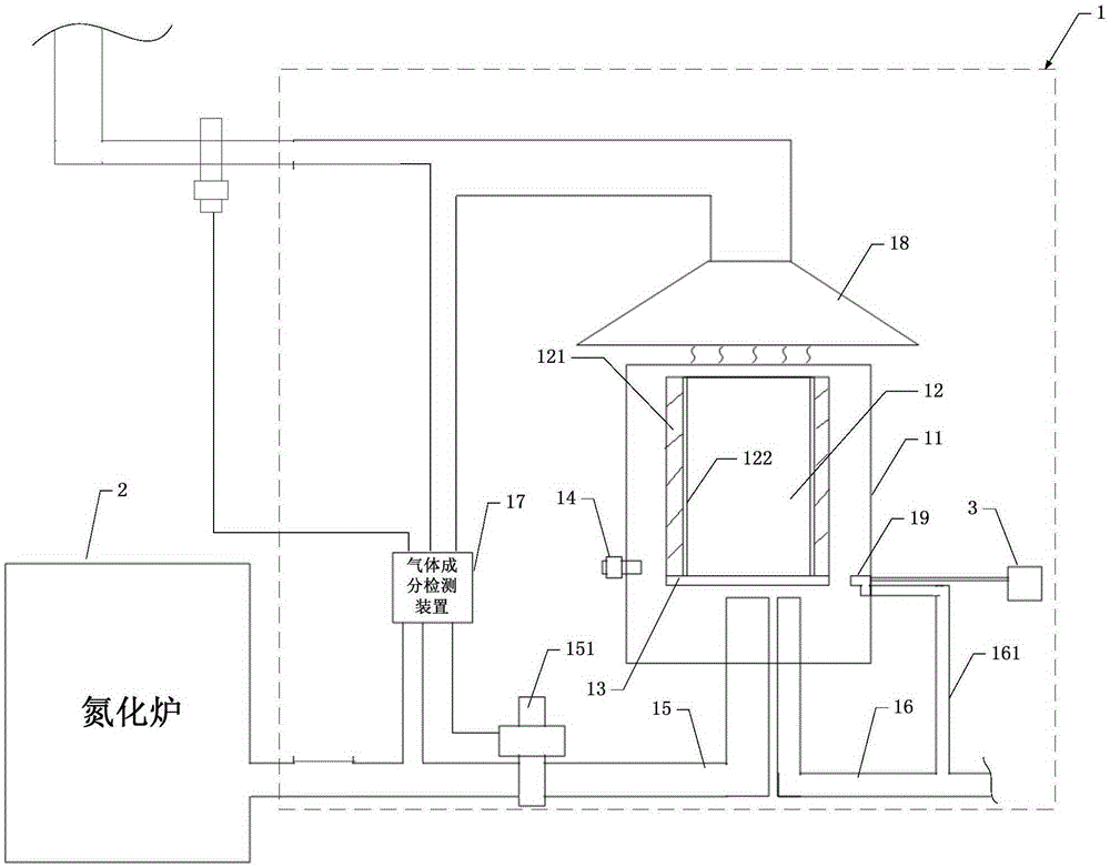
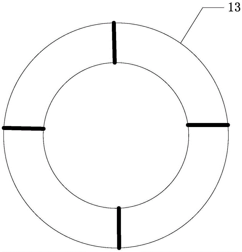
[0035] Such as figure 1 As shown, the present invention provides a waste gas treatment equipment 1 for nitriding furnaces, including: a device body 11 with an open upper end, and a combustion chamber 12 that penetrates up and down inside, and the bottom of the combustion chamber 12 is hollowed out or has ventilation The metal ring 13 of the hole, the metal ring 13 can be fixed by snapping or welding, and the device body 11 is also provided with: through the exhaust gas or closing the exhaust gas, the combustion chamber 12 can maintain the pressure required for the combustion of the exhaust gas. Pressure valve 14; exhaust gas transmission pipeline 15, connected to the nitriding furnace 2, and the gas outlet of the exhaust gas transmission pipeline 15 is sent from the bottom of the device body 11 to the combustion chamber 12, and is located under the metal ring 13 The gas outlet of the gas pipeline 16 communicates with the combustion chamber 12 from the bottom of the device body...


PUM

PropertyMeasurementUnit
thicknessaaaaaaaaaa
thicknessaaaaaaaaaa

Abstract

The invention provides a waste gas treatment device for a nitriding furnace. The waste gas treatment device comprises a device body of which the upper end is open, wherein a combustion chamber penetrating up and down is formed inside the device body; a metal ring which is hollowed out or provided with an air vent is arranged at the bottom of the combustion chamber; the device body is further provided with a pressure retaining valve which is capable of keeping the desired pressure for waste gas combustion through exhausting or shutdown of exhausting; the waste gas of the nitriding furnace is fed into the combustion chamber and below the metal ring from the bottom of the device body through a waste gas transmission pipeline, and the gas outlet of a gas pipeline is communicated with the combustion chamber and below the metal ring from the bottom of the device body; the gas out of the gas pipeline is ignited by an ignition device to heat the metal ring, the metal ring heats the combustion chamber so that the temperature in the combustion chamber is higher than the ignition temperature of the waste gas, and therefore, the waste gas transmission pipeline is communicated with the interior of the combustion chamber to burn the waste gas and emit the waste gas after combustion through a pipeline; and consequently, enough temperature and pressure in the combustion chamber are guaranteed to sufficiently burn the waste gas and avoid residual.

Description

technical field [0001] The invention relates to the technical field of waste gas treatment, in particular to waste gas treatment equipment for nitriding furnaces. Background technique [0002] Today, nitrogen treatment has become an indispensable part of metallurgical processing and other fields. However, after the nitriding furnace is used, there is often a part of waste gas left, such as ammonia (NH 3 ), etc., will pass through the gas (usually methane CH 4 ) combustion method to be processed (converted into NO 2 However, due to the high ignition point of ammonia, in actual situations, it often cannot be completely combusted, which will cause residual problems. Contents of the invention [0003] In view of the above-mentioned shortcomings of the prior art, the object of the present invention is to provide a waste gas treatment device for nitriding furnaces, so as to solve the above-mentioned problem of nitriding furnace waste gas treatment residues. [0004] In order ...

Claims


Application Information

Patent Timeline
Patent Type & Authority Patents(China)
IPC IPC(8): F23G7/06C23C8/24
Inventor 顾晓文赵玉宝夏再喜
Owner TONGFU HEAT TREATMENT KUNSHAN
Why Eureka
Try Eureka