Method for determining distance between block valve chambers of long-distance natural gas pipeline

A technology for long-distance pipelines and determination methods, applied in pipeline systems, gas/liquid distribution and storage, mechanical equipment, etc.

Inactive Publication Date: 2014-04-23
SOUTHWEST PETROLEUM UNIV
View PDF3 Cites 2 Cited by
  • Summary
  • Abstract
  • Description
  • Claims
  • Application Information

AI Technical Summary

Problems solved by technology
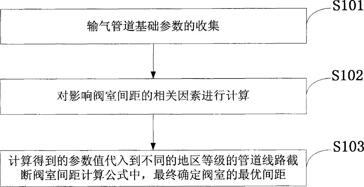
[0005] The purpose of the embodiment of the present invention is to provide a method for determining the distance between valve chambers of long-distance natural gas pipelines, aiming to solve the problem of how to adjust and design the standard for setting the distance between valve chambers

Method used


Image

  • Method for determining distance between block valve chambers of long-distance natural gas pipeline
  • Method for determining distance between block valve chambers of long-distance natural gas pipeline
  • Method for determining distance between block valve chambers of long-distance natural gas pipeline

Examples


Embodiment 1

[0162] Embodiment 1. According to the U.S. regional grading standard, determine the distance between line cut-off valve chambers of pipelines in grades 1, 2, 3 and 4, and compare with the ASME B31.8 standard to verify the accuracy of the present invention.

[0163] Table 5 Failure frequency of long-distance natural gas pipelines in the United States

[0164]

[0165] Table 6 Population Density of Regions of Different Levels in the United States

[0166] Level 1 area 1~10 households secondary area 11~45 households Tertiary area 46~100 households Level 4 area >=101 households

[0167] Note: In Table 6, the population of each household is 3 persons.

[0168] Table 7 Comparison between the calculated value and the standard value of valve chamber spacing in different grades of the United States (km)

[0169]

[0170]

[0171] According to the calculation results, it can be seen that the distance between the valve chambers calculated a...

Embodiment 2

[0172] Embodiment 2. In this example, the distance between the pipeline line cut-off valve chambers in the first-level and second-level areas is determined according to the regional classification standards of our country.

[0173] Table 8 Population Density of Regions of Different Levels in China

[0174] Level 1 area 1~15 households secondary area 16~99 households

[0175] Tertiary area 100-200 households Level 4 area >=201 households

[0176] Note: In Table 8, the population of each household is 3.1 persons

[0177] Table 9 Failure frequency and correction coefficient of natural gas pipelines damaged by third parties

[0178] District level Level 1 and Level 2 areas Frequency of failure due to third-party damage related to pipe diameter 0.135 Wall Thickness Correction Factor 1

[0179] position correction factor 1 Buried depth correction factor 1 Correction factor for protecti...


PUM


Abstract

The invention discloses a method for determining the distance between block valve chambers of a long-distance natural gas pipeline. The method comprises the step of collecting basic parameters of the gas pipeline, the step of analyzing related factors affecting the distance between the block valve chambers, and the step of establishing a pipeline block valve chamber distance computational mathematics model and determining the optimal distance between the valve chambers of different region grades. According to the method, firstly, the basic parameters such as the pipeline diameter, the wall thickness, the burial depth, the population density of the region where the pipeline is located, the region grade and the allowed natural gas potential emission load are collected; secondly, the third-party damage failure frequency, the failure consequence, the pipeline valve chamber design, the construction cost and the natural gas potential emission load of pipelines under different region grades are comprehensively taken into consideration, the optimal valve chamber distance calculation formula is determined, and therefore the valve chamber distance value is obtained. The method is reliable in result, easy to carry out, and a reliable method is provided for determining the reasonable valve chamber distance of the long-distance natural gas pipeline.

Description

technical field [0001] The invention belongs to the technical field of natural gas transportation, and in particular relates to a method for determining the interval between cut-off valve chambers of long-distance natural gas pipelines. Background technique [0002] Natural gas is a clean and efficient energy source. With the development of my country's economy and society, the demand for natural gas resources continues to increase. Pipeline transportation is one of the most efficient and economical methods of natural gas transportation. my country has built long-distance natural gas pipelines with a total length of more than 80,000 kilometers, including the West-to-East Gas Pipeline. However, natural gas is a combustible gas, its main component is methane, and its explosion limit with air is about 5% to 15%, and its leakage into the air can easily cause explosion and fire. Therefore, setting a shut-off valve chamber (a general term for a line shut-off valve and its suppor...

Claims


Application Information

Patent Timeline
Patent Type & Authority Applications(China)
IPC IPC(8): F17D1/00
Inventor 李长俊贾文龙廖柯熹李施奇李卓然吴瑕
Owner SOUTHWEST PETROLEUM UNIV
Why Eureka
Try Eureka