
Valve core component of automatic control valve

A technology for automatic control of valve and valve core components, applied in engine components, lift valves, valve details, etc., can solve the problems of resource waste, leakage, unreliable work, etc., and achieve the effect of not easy to leak

Active Publication Date: 2014-04-23
TIANJIN HUANENG THERMAL EQUIP
View PDF4 Cites 5 Cited by
  • Summary
  • Abstract
  • Description
  • Claims
  • Application Information

AI Technical Summary

Problems solved by technology

When the current automatic control valve is closed, the valve core is closed against the flow direction or pressure direction of the fluid medium, and the pressure action direction of the fluid medium is opposite to the closing direction of the valve core. After the valve is closed, the valve core needs to resist the fluid The pressure of the medium, therefore, is prone to failures due to poor closure and leakage, resulting in unreliable work that affects the normal operation of the equipment, short service life and waste of resources, and affects safety

Method used


Image

  • Valve core component of automatic control valve
  • Valve core component of automatic control valve
  • Valve core component of automatic control valve

Examples


Embodiment 1

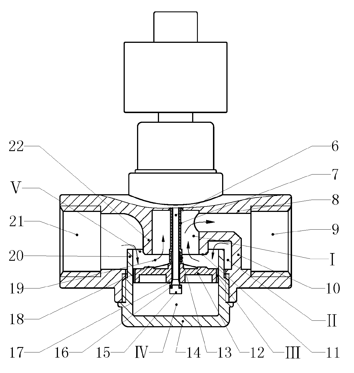
[0014] Embodiment 1 Attached figure 1In the shown embodiment, the spool assembly of the automatic control valve consists of a valve seat (22), a ring wall (20), a valve plate (12), a connecting rod (6) and a bottom cover (14), wherein the valve seat (22) is set in the inner cavity of the valve body (8), the valve seat (22) is a rotary structure, the upper end of the valve seat (22) is connected with the valve body (8), and the lower port of the valve seat (22) Constitute the sealing surface (11), the inner space of the valve seat (22) constitutes the upper valve chamber (I), and the upper valve chamber (I) is connected to the fluid output port (9) of the valve body (8); the ring wall (20) is set Below the valve seat (22), the upper port of the ring wall (20) surrounds the lower periphery of the valve seat (22), the lower end of the ring wall (20) is connected to the bottom cover (14), and the ring wall (20) and There is a space between the valve seats (22), the space between ...

Embodiment 2

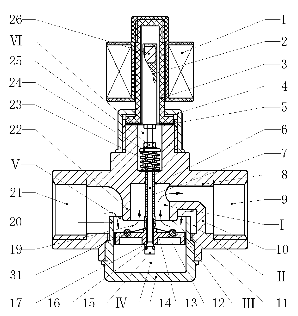
[0015] Embodiment 2 Attached figure 2 In the shown embodiment, the electromagnetic valve composed of the valve core assembly of the present invention mainly consists of a valve seat (22), a ring wall (20), a valve plate (12), a connecting rod (6), a bottom cover (14), an electromagnetic Coil (1), guide rod (2), magnetic sleeve (3), magnet (26) and spring (23), wherein, the valve seat (22) is set in the inner cavity of the valve body (8), the valve The seat (22) is a revolving body structure, the upper end of the valve seat (22) is connected with the valve body (8), the lower port of the valve seat (22) forms the sealing surface (11), and the inner space of the valve seat (22) forms The upper valve cavity (I), the upper valve cavity (I) is connected to the fluid output port (9) of the valve body (8); the ring wall (20) is set under the valve seat (22), and the upper The port surrounds the lower periphery of the valve seat (22), the lower end of the ring wall (20) is connected...

Embodiment 3

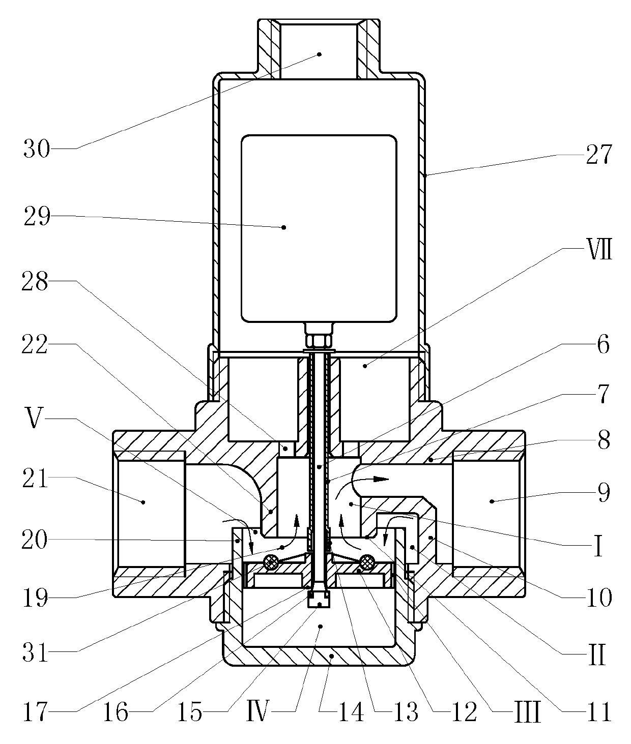
[0016] Example 3 Attached image 3 In the embodiment shown, an automatic liquid level control valve composed of the valve core assembly of the present invention mainly consists of a valve seat (22), a ring wall (20), a valve plate (12), a connecting rod (6), a bottom cover (14), the float (29) and the wall (27) of the water chamber, wherein the valve seat (22) is set in the inner cavity of the valve body (8), the valve seat (22) is a rotary structure, and the valve seat The upper end of (22) is integrated with the valve body (8), the lower port of the valve seat (22) constitutes the sealing surface (11), the inner space of the valve seat (22) constitutes the upper valve chamber (I), and the upper valve chamber ( Ⅰ) Connected to the fluid output port (9) of the valve body (8); the ring wall (20) is set under the valve seat (22), and the upper port of the ring wall (20) surrounds the lower periphery of the valve seat (22) , the lower end of the ring wall (20) is connected to th...


PUM


Abstract

The invention discloses a valve core component of an automatic control valve, and relates to a valve component. The valve core component consists of a valve seat, a ring wall, a valve plate, a connection rod and a bottom cover, wherein the valve seat is arranged in the inner cavity of the valve body and adopts a rotating body structure; the lower end opening of the valve seat forms a sealing surface; an upper valve cavity is formed in the inner space of the valve seat and is communicated to a fluid output connection opening; the ring wall is arranged below the valve seat; the upper end opening of the ring wall surrounds the periphery of the lower part of the valve seat; a flow guide opening is formed in a space between the ring wall and the valve seat; a lower valve cavity is formed in the inner space of the ring wall; a fluid input connection opening is communicated to the lower valve cavity through the flow guide opening; the valve plate is arranged in the lower valve cavity and is positioned below the flow guide opening; a sealing corresponding surface matched with the sealing surface on the valve seat is arranged on the upper end face of the valve plate. The valve is switched on by down flow of a fluid medium and is switched off by down pressure of the fluid medium, so that the valve core component can save electric energy, works reliably and is long in service life.

Description

technical field [0001] The invention relates to a valve for automatically controlling fluid, in particular to a valve part. Background technique [0002] Automatic control valves include solenoid valves, automatic liquid level control valves, etc. Automatic control valves are widely used in household appliances, textiles, light industry, petroleum, chemical and urban construction industries as actuators for automatic control of fluid media. When the current automatic control valve is closed, the valve core is closed against the flow direction or pressure direction of the fluid medium, and the pressure action direction of the fluid medium is opposite to the closing direction of the valve core. After the valve is closed, the valve core needs to resist the fluid The pressure of the medium, therefore, is prone to failures due to poor closure and leakage, resulting in unreliable work that affects the normal operation of the equipment, short service life and waste of resources, an...

Claims


Application Information

Patent Timeline
Patent Type & Authority Applications(China)
IPC IPC(8): F16K1/00F16K1/36F16K1/42F16K27/02
CPCF16K1/00F16K1/36F16K1/42F16K1/46F16K1/48F16K27/02
Inventor 周昀煜
Owner TIANJIN HUANENG THERMAL EQUIP
Learn More