
Flowing type efficient spiral material leveling machine

A leveling machine and flow-type technology, applied in the field of construction machinery, can solve the problems of large space, small operating range, and low efficiency, and achieve the effects of strong adaptability, good closing effect, and high efficiency

Active Publication Date: 2014-04-23
WUHAN K CRANE OCEAN ELEVATORING TECH
View PDF7 Cites 4 Cited by
  • Summary
  • Abstract
  • Description
  • Claims
  • Application Information

AI Technical Summary

Problems solved by technology

[0004] At present, most of the leveling operations of bulk materials in train cars are carried out by workers holding nail rakes. This method of leveling is labor-intensive, inefficient and expensive.
However, there are not many special mechanical equipments applicable to the leveling operation of the above-mentioned carriage stockpile and there are some deficiencies, such as Yang Zhong’s invention patent elevated rail-type spiral high-efficiency leveling system (patent number: 2012105342256), and its leveling machine Supported on the mast, the whole system is fixed, and the operating range of the leveling machine is small, and the carriage to be closed can only be pulled to the bottom of the mast for the unwinding operation, so the train must be moved many times during the unwinding operation; at the same time, the The gantry structure of the system is relatively large, and the lifting mechanism cannot be retracted, so the use space is relatively large

Method used


Image

  • Flowing type efficient spiral material leveling machine
  • Flowing type efficient spiral material leveling machine
  • Flowing type efficient spiral material leveling machine

Examples


Embodiment Construction

[0030] The present invention will be further described below in conjunction with the embodiments and accompanying drawings.

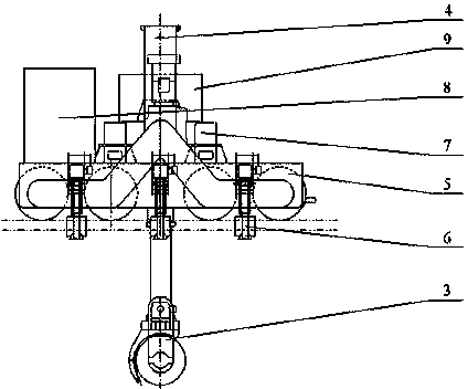
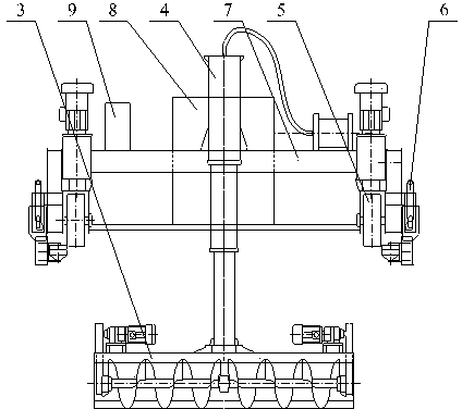
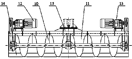
[0031] Such as figure 1 , figure 2 As shown, it includes: a screw pushing mechanism 3, a lifting mechanism 4, a traveling mechanism 5, an anti-deviation mechanism 6, a frame 7, a power device 8, an electric control device 9, and a control device. In the embodiment of the present invention, the power device 7 is a generator. The screw leveling machine is powered by its own generator, and uses the side of the train carriage 2 as a track to walk on the carriage 2, and unwind the materials in the carriage 2 above the carriage 2. At the same time, it can also complete a certain height difference and width interval. The cross-car movement realizes the leveling of the whole train.

[0032] Such as Figure 7 , Figure 8 As shown, two sets of running gear 5 include wheel set 19, walking drive device 20 and sprocket wheel set 21 in total. A set of whee...


PUM


Abstract

The invention discloses a flowing type efficient spiral material leveling machine. When the flowing type efficient spiral material leveling machine operates, travelling mechanisms are horizontally arranged on bilateral sideboards in the width direction of a train; a plurality of groups of incline proof mechanisms are connected to external sides of the travelling mechanisms through bolts; incline proof lateral rolling wheel groups which are arranged on external sides of the sideboards play roles in preventing the material leveling machine travelling from deorbiting; lifting mechanism supports are fixedly connected to symmetrical bases which are arranged at end beams at upper ends of the travelling mechanisms; ladder-shaped structures of the lifting mechanism supports are formed due to the fact that two short square steel are symmetrically welded to the middle of two long square steel perpendicularly; lifting mechanisms perpendicularly penetrate frame-shaped areas which are defined by the two short square steel and the long square steel; spiral material pushing mechanisms which are connected under the lifting mechanisms are perpendicular to rails in the length direction. According to the flowing type efficient spiral material leveling machine, power is supplied through a built-in power device, travelling and carriage crossing are directly performed on a carriage with the train sideboards serving as the rails, and scanning type cabin leveling operation of all carriages of the integral train is achieved. The flowing type efficient spiral material leveling machine has the advantages of completely replacing manual cabin leveling operation, meanwhile satisfying cabin leveling tasks at any places, being good in cabin leveling effect, high in efficiency, strong in adaptability, safe and reliable and the like.

Description

technical field [0001] The invention relates to a construction machine, in particular to a flow-type high-efficiency screw flat feeder. Background technique [0002] Bulk materials such as ore and coal are often transported by train for long distances. During the process of loading the bulk materials into the train carriages through the loading building or loading trucks, the accumulation characteristics of the bulk materials determine that the materials will form a pile with a sharp top in the middle of the carriages. When the train passes through a curve during transportation, due to the effect of centrifugal force, the sharp-edged material pile in the carriage will be thrown to one side of the carriage, resulting in unbalanced material loading on both sides of the carriage. In this situation, when the train passes through the curve at high speed, the materials are easy to spill out of the carriage, causing material loss and environmental pollution. In severe cases, the c...

Claims


Application Information

Patent Timeline
IPC IPC(8): B65G69/04
Inventor 杨仲
Owner WUHAN K CRANE OCEAN ELEVATORING TECH
Learn More