
A drone onboard power generation equipment

A technology for power generation equipment and drones, applied in the field of drones, can solve problems such as difficulty, confusion of data parameters, and heavy weight of onboard power generation devices, and achieve the effects of improving power supply status, ensuring work performance, and stable and reliable signals

Active Publication Date: 2015-11-18
天津全华时代航天科技发展有限公司
View PDF6 Cites 0 Cited by
  • Summary
  • Abstract
  • Description
  • Claims
  • Application Information

AI Technical Summary

Problems solved by technology

[0002] At present, the power of the UAV is provided by the on-board battery. The larger the battery, the greater the load on the UAV, and the longer the flight time, the more power it needs. Its load causes more waste of electric energy
[0003] Airborne power generation equipment has not yet been applied in the field of UAVs, and the airborne power generation devices used in existing aviation equipment are usually heavy in weight and large in size, which is difficult to be directly applied to UAVs, and the generated voltage is unstable. This caused the communication of the autopilot to be greatly affected
Due to the instability of various parameters sent, it is easy to cause confusion of various data parameters, which affects the effect and quality of the drone's ground control and aerial photography
Moreover, due to the limited battery capacity of the current UAV, there are more and more electronic devices in the aircraft, the problem of power supply of electronic devices, and the problem of flight endurance can no longer meet the needs of multi-power, full-electricity and long-term flight of UAVs. It will be more difficult to provide enough power for the aircraft to fly directly from the limited battery of the aircraft

Method used


Image

  • A drone onboard power generation equipment
  • A drone onboard power generation equipment
  • A drone onboard power generation equipment

Examples


example

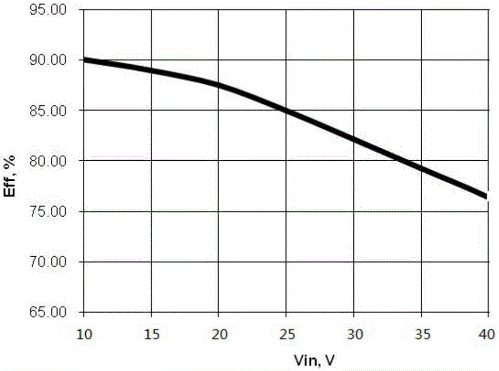
[0045] Example: A toothed belt drives a generator, the gear ratio between the two gears can be chosen to keep the input voltage of the on-board power generation unit (AGPU) within the 36V limit. In many cases, the low engine RPM results in a voltage lower than 12V, which means that the backup battery will power the UAS, and the UAV flying at low speed will be powered by the backup battery for the extra time. According to the actual flight mission, the capacity of the battery needs to be calculated. Battery capacity (Ah) = working time (h) * average load power (W) / battery voltage (V) / 0.8.

[0046] In the present invention, the on-board power generation unit (AGPU) has two electronic aviation interfaces.


PUM


Abstract

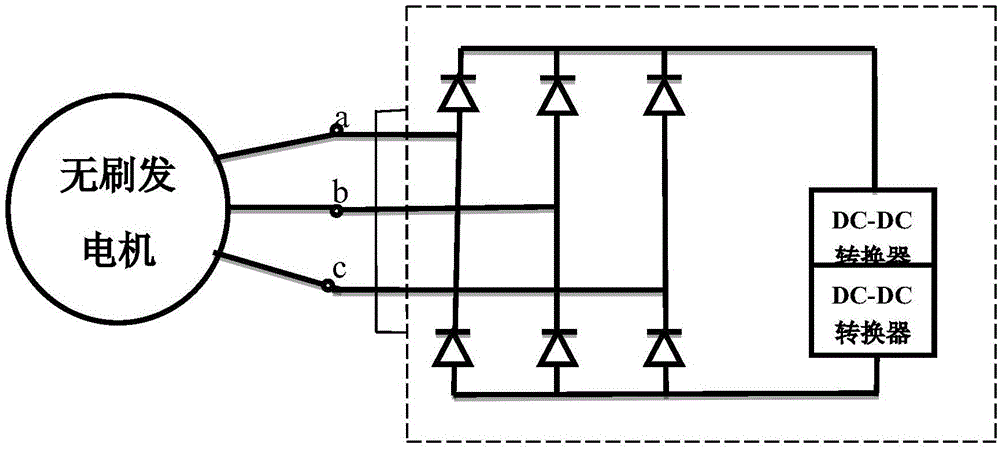
The invention relates to onboard power generation equipment of an unmanned aerial vehicle. The onboard power generation equipment comprises a brushless generator, a three-phase alternating current rectifier, a 5V DC-DC module, a 12V DC-DC module and a lithium iron phosphate battery. The onboard power generation equipment is characterized in that the brushless generator is connected with the DC-DC modules through the three-phase alternating current rectifier, the 5V DC-DC module and the 12V DC-DC module are both connected with the lithium iron phosphate battery in parallel, the 5V DC-DC module is connected with a steering engine, and the 12V DC-DC module is connected with a self-driving instrument, a radio station and a pan-tilt camera. The onboard power generation equipment is direct-current power supply equipment which supplies two voltages to the unmanned aerial vehicle, so that the unmanned aerial vehicle has super-long continuous flight time; the onboard power generation equipment is small in size, light in weight, and capable of providing efficient electric energy and stable voltages; the onboard power generation equipment is in communication with the self-driving instrument on the unmanned aerial vehicle to transmit the engine revolution, the generating voltage, load power distribution parameters and the like to a ground station during flight, and signals are stable and reliable.

Description

technical field [0001] The invention belongs to the field of unmanned aerial vehicles and relates to power generation of unmanned aerial vehicles, in particular to an onboard power generation equipment of unmanned aerial vehicles. Background technique [0002] At present, the power of the UAV is provided by the on-board battery. The larger the battery, the greater the load on the UAV, and the longer the flight time, the more power it needs. Its load causes more waste of electric energy. [0003] Airborne power generation equipment has not yet been applied in the field of UAVs, and the airborne power generation devices used in existing aviation equipment are usually heavy in weight and large in size, which is difficult to be directly applied to UAVs, and the generated voltage is unstable. This caused the communication of the autopilot to be greatly affected. Due to the instability of various parameters sent, it is easy to cause confusion of various data parameters, which af...

Claims


Application Information

Patent Timeline
Patent Type & Authority Patents(China)
IPC IPC(8): B64D47/00H02J7/34
Inventor 权军
Owner 天津全华时代航天科技发展有限公司
Learn More