Techniques for efficient power transfers in a capacitive wireless powering system

A power supply system, capacitive technology, applied in the field of capacitive power supply system, can solve the problem that conductive material and size cannot be optimized to support the load, the system cannot be optimized for two loads, etc., to achieve the effect of efficient power transmission

Inactive Publication Date: 2014-04-16
KONINKLJIJKE PHILIPS NV
View PDF4 Cites 10 Cited by
  • Summary
  • Abstract
  • Description
  • Claims
  • Application Information

AI Technical Summary

Problems solved by technology

Furthermore, the system cannot be optimized to support both loads since each load has different drive power properties
Furthermore, the conductive material and dimensions of the transmitter electrodes cannot be optimized to support the corresponding load

Method used


Image

  • Techniques for efficient power transfers in a capacitive wireless powering system
  • Techniques for efficient power transfers in a capacitive wireless powering system
  • Techniques for efficient power transfers in a capacitive wireless powering system

Examples


Embodiment Construction

[0021] It is important to point out that the disclosed embodiments are merely examples of the many advantageous uses of the innovative teachings herein. In general, statements made in the specification of the present application do not necessarily limit any of the claimed inventions. Furthermore, some statements may apply to some inventive features but not to others. In general, unless indicated otherwise, singular elements may be plural and vice versa without loss of generality. In the figures, like reference numerals denote like parts throughout the several views.

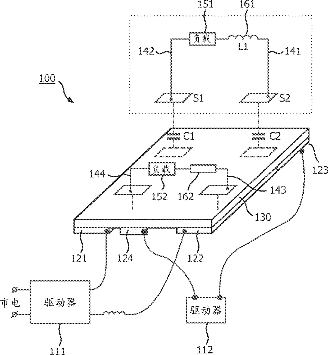
[0022] figure 1 A schematic diagram of a capacitive powering system 100 is shown, which is utilized to describe various embodiments of the invention. The system 100 enables large area power transfer and can be installed in places such as bathrooms where open electrical contacts are not preferred or desired, or in retail stores where regular lighting movements and changes are required to Illuminate products, f...


PUM


Abstract

A capacitive powering system(100) comprises a low power driver (111), a high power driver (112), a plurality of pairs of transmitter electrodes separated into a plurality of power sub-areas (210-1, 210-N) including at least a group of high power sub-areas (210-1, 210-M) connected to the high power driver and a group of low power sub-areas (210-M+1, 210-N) connected to the low power driver, and an insulating layer (130) having a first side and a second side opposite to each other, the pairs of plurality of transmitter electrodes are coupled to the first side of the insulating layer. The system is configured to forma capacitive impedance between the pairs of plurality of transmitter electrodes and a plurality of pairs of receiver electrodes (141, 144) placed in proximity to the second side of the insulating layer to wirelessly power each load connected to each of the pair of receiver electrodes.

Description

[0001] This application claims priority to US Provisional Application Nos. 61 / 523,928 and 61 / 523,929, filed August 16, 2012, and US Provisional Application No. 61 / 622,102, filed August 10, 2012. technical field [0002] The present invention relates generally to capacitive power systems for wireless power transfer, and more particularly to structures for allowing efficient power transfer in large area wireless power systems including hotspots. Background technique [0003] Wireless power transmission refers to the supply of power without any connection or contact, so the power supply of electronic devices is performed through a wireless medium. One common application for contactless power supply is for charging portable electronic devices such as mobile phones, laptop computers and the like. [0004] One implementation for wireless power transfer is through inductive powering systems. In such systems, electromagnetic induction between a source (transmitter) and a device (re...

Claims


Application Information

Patent Timeline
IPC IPC(8): H04B5/00H02J17/00
CPCH04B5/0012H01F38/14H04B5/0037H02J17/00H02J50/05H02J50/402H02J50/10H04B5/22H04B5/79
Inventor D.W.范古尔A.塞姆佩尔E.瓦芬施密特H.T.范德詹登
Owner KONINKLJIJKE PHILIPS NV
Why Eureka
Try Eureka