A DC transmission commutation failure defense method based on current limitation method
A technology of commutation failure and direct current transmission, which is applied in the field of power transmission and distribution, can solve the problems of increasing the power factor of the AC fault direct current direct current transmission system, and achieve the reduction of secondary commutation failure, which is conducive to recovery and commutation The effect of area reduction
Active Publication Date: 2015-09-23
NORTH CHINA ELECTRIC POWER UNIV (BAODING) +3
View PDF5 Cites 0 Cited by
- Summary
- Abstract
- Description
- Claims
- Application Information
AI Technical Summary
Problems solved by technology
To sum up, the existing defense methods have a certain effect on DC transmission system against commutation failure, but they will increase the DC current during the AC fault process and reduce the power factor of the DC transmission system, which may sometimes lead to negative results
Method used
View moreImage
Smart ImageViewing Examples


Examples
Embodiment Construction
Login to View More PUM
 Abstract
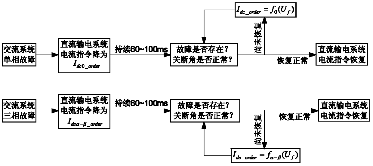
The invention provides a defense method for commutation failures of direct-current transmission based on a current limiting method. The method comprises the following steps: I, according to an output signal of failure detection, detecting the failure type of a commutation bus of a direct-current transmission system; II, by using the current limiting method, reducing a direct-current instruction and continuing for 60-100 ms; III, judging whether a failure is eliminated and a turn-off angle of the direct-current transmission system is restored; and IV, determining the direct-current instruction according to a judgment result until the failure is eliminated, and restoring the direct-current instruction. According to the method, adverse effects such as increasing a direct-current, increasing a power factor angle of the direct-current transmission system, and the like caused by advanced triggering are avoided, and a timely and effective response is made to an alternating-current system failure, so that the required commutation area of a thyristor is reduced, thereby facilitating that the direct-current transmission system is prevented from having commutation failures.
Description
technical field The invention relates to a method in the technical field of power transmission and distribution, in particular to a method for preventing commutation failure of direct current transmission based on fast current limitation. Background technique Since the 1950s, the traditional line-commutated-converter high-voltage direct current (LCC-HVDC) has gained rapid popularity worldwide due to its large-capacity long-distance power transmission and fast controllable active power. development of. However, since LCC-HVDC uses ordinary thyristors without self-shutoff capability as commutation components, the LCC-HVDC system requires a certain strength of the AC system to achieve commutation, and the commutation voltage needs to be provided by the AC grid. When the power grid fails or the three-phase is seriously asymmetrical, the AC bus voltage will drop, the line voltage zero crossing point may be advanced, the commutation overlap angle of the LCC-HVDC valve arm will ...
Claims
Login to View More Application Information
Patent Timeline
 Patent Type & Authority Patents(China)
IPC IPC(8): H02J3/36G01R31/08
CPCY04S10/522Y02E60/60Y04S10/52
Inventor 郭春义刘羽超赵成勇李春华张庆国许韦华阳岳希刘奕斌井雨刚
Owner NORTH CHINA ELECTRIC POWER UNIV (BAODING)
Features
- R&D
- Intellectual Property
- Life Sciences
- Materials
- Tech Scout
- Unparalleled Data Quality
- Higher Quality Content
- 60% Fewer Hallucinations
Learn More Browse by: Latest US Patents, China's latest patents, Technical Efficacy Thesaurus, Application Domain, Technology Topic, Popular Technical Reports.
© 2025 PatSnap. All rights reserved.Legal|Privacy policy|Modern Slavery Act Transparency Statement|Sitemap|About US| Contact US: help@patsnap.com