
A Method of Suppressing Deceptive False Target Interference Using Active and Passive Radar Network Configured in Different Places

An active radar and passive radar technology, applied in the field of radar technology, can solve the problems of high probability of misidentification of deceptive false targets, reduce the probability of misidentification of active and passive radar networks, etc., and achieve the effect of reducing the probability of misidentification

Active Publication Date: 2016-01-13
XIDIAN UNIV
View PDF2 Cites 0 Cited by
  • Summary
  • Abstract
  • Description
  • Claims
  • Application Information

AI Technical Summary

Problems solved by technology

[0005] The purpose of the present invention is to solve the problem that the above-mentioned existing method has a higher probability of misidentifying deceitful false targets, and proposes a method for suppressing the interference of deceptive false targets with an active and passive radar network configured in different places, so as to effectively reduce the frequency of active and passive radars. Probability of Misidentification of False Objects by Network

Method used


Image

  • A Method of Suppressing Deceptive False Target Interference Using Active and Passive Radar Network Configured in Different Places
  • A Method of Suppressing Deceptive False Target Interference Using Active and Passive Radar Network Configured in Different Places
  • A Method of Suppressing Deceptive False Target Interference Using Active and Passive Radar Network Configured in Different Places

Examples


Embodiment Construction

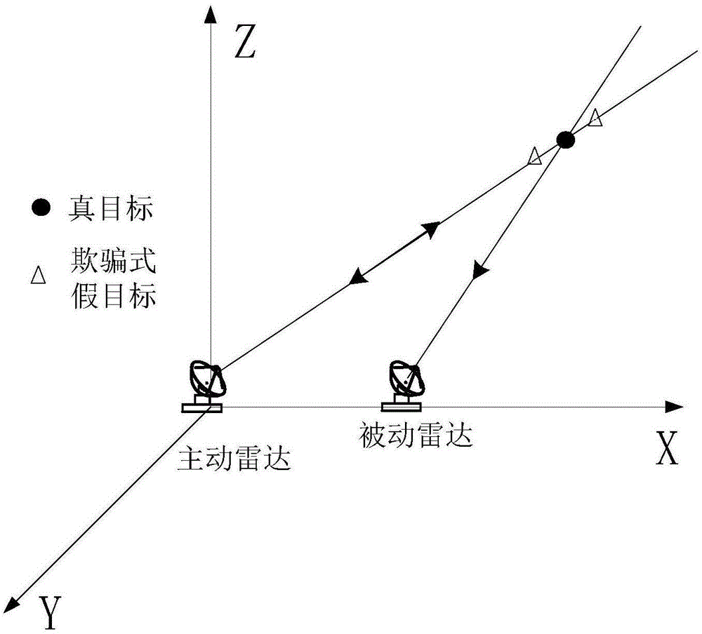
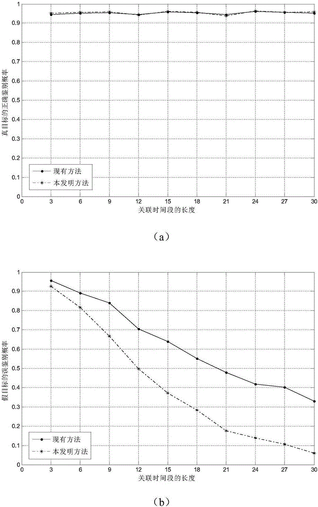
[0036] refer to figure 1 , the specific implementation steps of the present invention are as follows:

[0037] Step 1: Use the active radar in the active and passive radar network to detect the target, and obtain the measured value Zi(k) of each target of the active radar at different times:

[0038]

[0039] Among them, i represents the serial number of the target in the active radar, i=1,2,...,M, M is the number of targets detected by the active radar, k represents the time point, k=1,2,...,T , T is the total time point length of active and passive radar network detection time, r i (k), θ i (k), are the radial distance, azimuth angle, and elevation angle of the i-th target relative to the active radar at the k-th moment, respectively.

[0040] Step 2: Use the passive radar in the active and passive radar network to detect the target, and obtain the measurement value G of each target of the passive radar at different times j (k):

[0041]

[0042] Among them, j r...


PUM


Abstract

The invention discloses a method for restraining deception false target jamming through a remotely configured initiative and passive radar net. The method for restraining the deception false target jamming through the remotely configured initiative and passive radar net mainly solves the problem that the prior art is high in false target error identification probability. The method for restraining the deception false target jamming through the remotely configured initiative and passive radar net comprises steps of 1, detecting a target through an initiative radar and a passive radar in the initiative and passive radar net and obtaining a measuring value of the target; 2, computing an estimated value and an error covariance matrix of a measuring value of the passive radar through a measuring value of the initiative radar; 3, computing the correlation distance of all targets of the initiative radar and the passive radar at different moments according to the estimated value and a target measuring value of the measuring value of the passive radar and accordingly obtaining identification statistics; 4, setting a detection threshold, comparing the identification statistics with the threshold and obtaining a correlation detection result; 5, performing ambiguity processing on the correlation detection result, performing true and false judgment on all the targets of the initiative radar through the processed result and removing false targets. The method for restraining the deception false target jamming through the remotely configured initiative and passive radar net reduces the error identification probability of the false targets and effectively achieves restraining of the deception false targets.

Description

technical field [0001] The present invention relates to the field of radar technology, in particular to deceptive interference countermeasure technology, and specifically to a method for suppressing deceptive false target interference using an active and passive radar network configured in different places. The method can be used in the data fusion center of the active and passive radar network, through Point trace correlation test, identify and eliminate deceptive false target interference, improve the detection and tracking performance of active and passive radar networks under deceptive false target interference. Background technique [0002] The active jamming that can be carried out by jammers on radar is divided into suppressive jamming and deceptive jamming. Since deceptive jamming can use the pulse compression gain of the radar receiver, the jamming efficiency is high, and it has attracted widespread attention. In particular, the emergence of digital radio frequency ...

Claims


Application Information

Patent Timeline
Patent Type & Authority Patents(China)
IPC IPC(8): G01S7/36
CPCG01S7/021G01S7/36
Inventor 周宇赵永红赵珊珊张林让张娟
Owner XIDIAN UNIV
Learn More