
Method for simulation foundation pit excavation inner supporting experiments on basis of simple soil engineering centrifugal machine and special clamp thereof

A technology of geotechnical centrifuges and experimental methods, applied in the direction of machine/structural component testing, measuring devices, instruments, etc., can solve the problem of inability to simulate and reflect on-site excavation conditions well, hydraulic system leakage, and affect test results and other issues to achieve the effect of ensuring accuracy, convenient installation and operation, and simple working principle

Inactive Publication Date: 2014-04-16
SOUTHWEST JIAOTONG UNIV
View PDF6 Cites 11 Cited by
  • Summary
  • Abstract
  • Description
  • Claims
  • Application Information

AI Technical Summary

Problems solved by technology

This system uses soil substitute liquid instead of the on-site soil, which cannot simulate and reflect the excavation conditions on site well; the support structure uses hydraulic devices, which are relatively complicated, and the hydraulic system may leak liquid under the action of high centrifugal force, affecting test results

Method used


Image

  • Method for simulation foundation pit excavation inner supporting experiments on basis of simple soil engineering centrifugal machine and special clamp thereof
  • Method for simulation foundation pit excavation inner supporting experiments on basis of simple soil engineering centrifugal machine and special clamp thereof
  • Method for simulation foundation pit excavation inner supporting experiments on basis of simple soil engineering centrifugal machine and special clamp thereof

Examples


Embodiment Construction

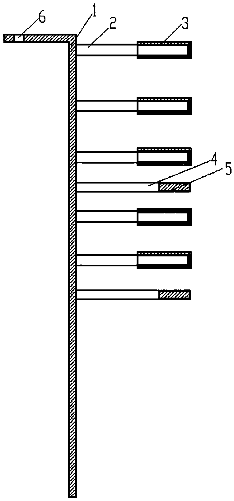
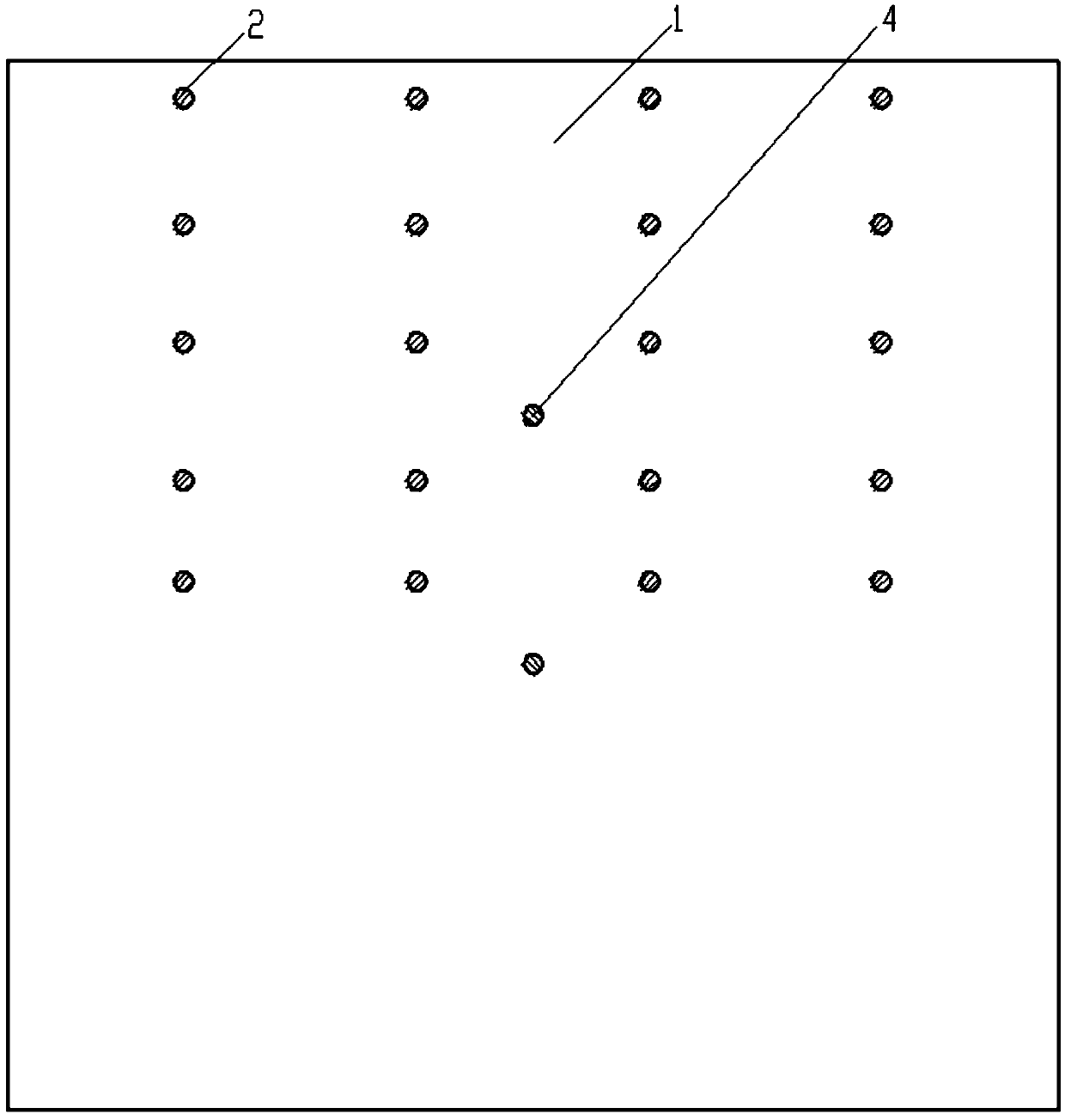
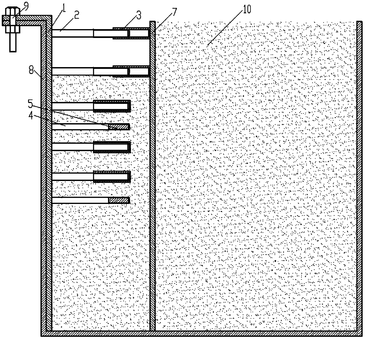
[0022] Figure 1~3 A specific embodiment of the invention is given. according to figure 1 , a geotechnical centrifuge test simulation foundation pit excavation internal support fixture, which consists of: fixed plate 1, internal support screw 2, external screw nut 3, displacement gauge support screw 4, laser displacement gauge 5 and so on. The fixed plate is made up of a steel plate, and a row of fixed screw holes 6 is reserved for extending out of the right end, which is used for fixing with the model box 8. It is required that the fixed screw hole 6 should be the same size as the screw hole on the model box 8, and the bolts 9 should be used to connect the two, such as figure 2 shown. The inner support screws 2 are arranged in four rows and five columns at a certain interval, and the cross-sectional area of ​​the steel bar in each row is the same, (the area is converted according to the compressive stiffness (EA) of the material (reinforced concrete or section steel) used...


PUM


Abstract

The invention discloses a method for simulation foundation pit excavation inner supporting experiments on the basis of a simple soil engineering centrifugal machine and a special clamp thereof. The method comprises the steps of vertically excavating left soil mass layer by layer in a layered mode, adjusting a supporting mechanism layer by layer so that the supporting mechanism can abut against a supporting plate, utilizing a displacement detection device placed on a next stage soil mass layer to collect displacement of the supporting plate, starting a centrifugal machine experiment, stopping the experiment until displacement is stabilized, and taking out a model box; excavating a second layer of soil mass, and performing a centrifugal machine experiment after excavation of the second layer of soil mass; and repeating the operation until a final layer of soil mass is excavated. Lateral movement of every working condition stage in the foundation pit excavation process can be accurately measured, and the measurement can be used for guiding actual foundation pit excavation. The simulation foundation pit excavation working conditions are the same as actual working conditions, and simulation experiment accuracy is guaranteed; a working principle is simple, a device is simple, the method has convenience in installing operation, and the clamp with different inner supporting screw welding positions can be manufactured according to different model box sizes and different engineering projects.

Description

technical field [0001] The invention relates to a model test of a geotechnical centrifuge and deep foundation pit engineering, in particular to an internal support fixture for simulating excavation of a deep foundation pit for a model test of a geotechnical centrifuge. Background technique [0002] Deep foundation pit is a large zero-time structure excavated at the proposed site before the construction of deep foundations and underground buildings. During the excavation of the foundation pit, due to the stress redistribution within the influence range of the foundation soil, the pit wall has a lateral displacement into the pit. Excessive lateral displacement may cause the pit wall to collapse or affect the normal use of surrounding buildings. In the construction process of large urban underground space structures, such as subway stations, underground parking lots, underground shopping malls, etc., due to the limitation of the site area, it is difficult to control the latera...

Claims


Application Information

Patent Timeline
Patent Type & Authority Applications(China)
IPC IPC(8): G01M99/00
Inventor 崔凯吕和林周庆黄邦文黄辉杨烨李欢欢
Owner SOUTHWEST JIAOTONG UNIV
Learn More