A supporting device for a wheel belt of a revolving body

A supporting device and rotary body technology, which is applied in transmission devices, drum furnaces, dry solid materials, etc., can solve the problems of contact surface wear, cylinder deformation, and unsuitable tire clearance, so as to improve the service life and prevent shaft The effect of moving to the movement and saving maintenance costs

Active Publication Date: 2016-03-23
NANNING GOOD FORTUNE HEAVY INDS
View PDF5 Cites 0 Cited by
  • Summary
  • Abstract
  • Description
  • Claims
  • Application Information

AI Technical Summary

Problems solved by technology

[0002] Rotary equipment such as rotary kiln, rotary dryer and rotary cooler are often used in the building materials industry, chemical industry and metallurgical industry. In order to avoid the necking phenomenon of the cylinder when the cylinder is thermally expanded, the rotary equipment mostly adopts loose sleeve tires. That is, an appropriate gap should be reserved between the tire and the backing plate, but due to the relative sliding between the tire and the backing plate, the contact surface has a certain wear and tear. The longer the use time, the larger the gap and the faster the wear speed. The backing plate must be replaced after a certain period of time, and the gap between the tire and the cylinder is not suitable, and the cylinder is easy to deform
The existing backing plate structure usually adopts a fixed backing plate, and the backing plate is directly welded on the cylinder. When replacing the backing plate, the backing plate needs to be cut off one by one. When the cylinder is re-welded with a new backing plate, welding stress will be generated again, which will easily cause deformation of the cylinder
, Moreover, if the backing plate is slightly worn, the gap between the tire and the cylinder will change, which is not easy to control

Method used


Image

  • A supporting device for a wheel belt of a revolving body
  • A supporting device for a wheel belt of a revolving body
  • A supporting device for a wheel belt of a revolving body

Examples


Embodiment Construction

[0024] The present invention will be further described in detail below in conjunction with the accompanying drawings, so that those skilled in the art can implement it with reference to the description.

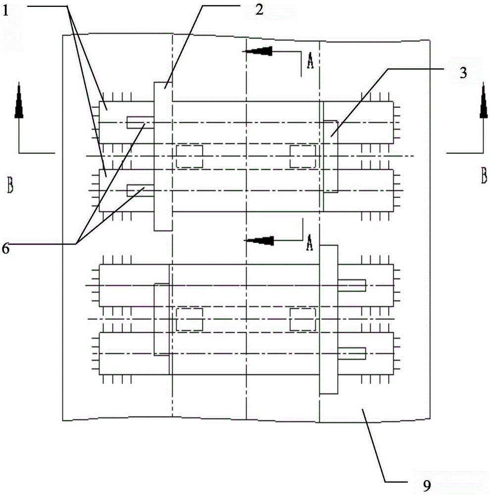
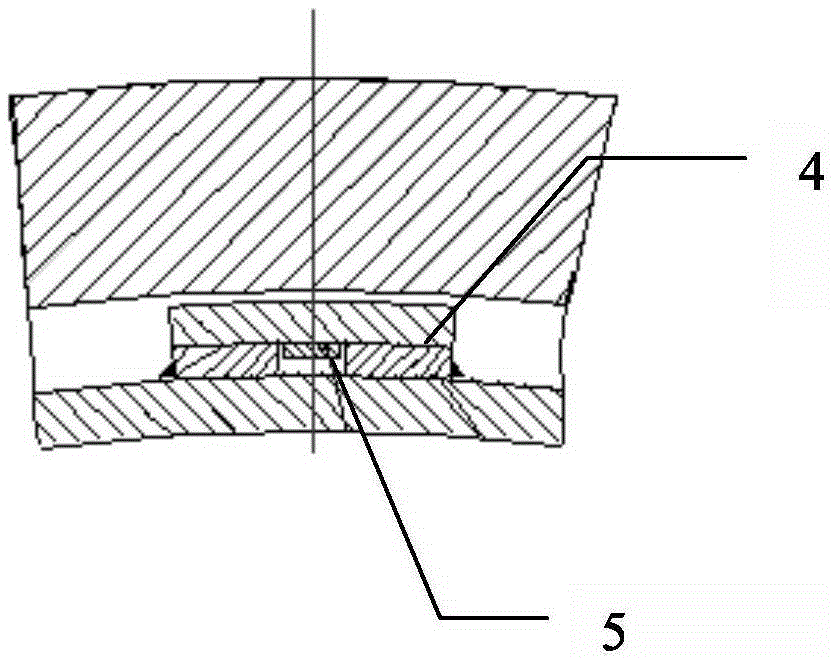
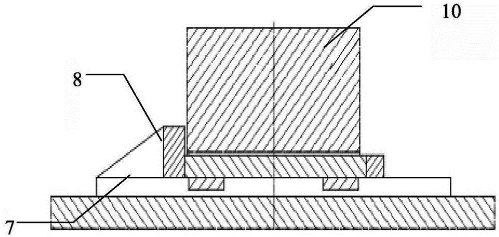
[0025] Such as Figure 1~4 As shown, a supporting device for a revolving wheel belt includes: a pair of first plates 1 , clamping parts, long fixing parts 2 and short fixing parts 3 , a fixing frame 11 , a cooling fan 12 and a control device 13 . A pair of first plate bodies 1 are fixed on the outer periphery of the rotary body 9 parallel to each other, and there is a first gap between the pair of first plate bodies 1 fixed on the outer periphery of the rotary body 9; the clamping part includes a second plate Body 4 and a pair of clamping blocks 5, a pair of clamping blocks 5 are fixed on the second plate body 4, the second plate body 4 is overlapped on a pair of first plate bodies 1, and a pair of clamping blocks 5 are clamped into the first gap ; fixed frame 11, which is f...


PUM


Abstract

The invention discloses a supporting device for a tire of a rotary body. The supporting device comprises a pair of first plates, a clamping part, a fixing frame, an air cooler, a control device and a processor. The lower surfaces of the first plates are fixed to the outer circumference of the rotary body, and a first gap is formed between the first plates. The clamping part comprises a second plate and clamping blocks. The clamping blocks are fixed to the second plate. The second plate is in lap joint on the first plates. The clamping blocks are clamped into the first gap. The fixing frame enables the tire to be pressed down so as to reduce the gap between the tire and the rotary body. The air cooler is arranged close to the rotary body and outputs cold air to surround the rotary body. The control device is used for controlling output of the air cooler. The control device comprises a temperature detector. The processor is used for controlling the air cooler to output the cold air when the temperature detector detects that the temperature of the rotary body rises. The supporting device is concise in structure and convenient to dismount, saves maintenance cost of equipment and prolongs the service life of the equipment.

Description

technical field [0001] The invention relates to a revolving body equipment, in particular to a revolving body wheel belt supporting device. Background technique [0002] Rotary equipment such as rotary kiln, rotary dryer and rotary cooler are often used in the building materials industry, chemical industry and metallurgical industry. In order to avoid the necking phenomenon of the cylinder when the cylinder is thermally expanded, the rotary equipment mostly adopts loose sleeve tires. That is, an appropriate gap should be reserved between the tire and the backing plate, but due to the relative sliding between the tire and the backing plate, the contact surface has a certain wear and tear. The longer the use time, the larger the gap and the faster the wear speed. The backing plate must be replaced after a certain period of time, and the gap between the tire and the cylinder is not suitable, and the cylinder is easily deformed. The existing backing plate structure usually adop...

Claims


Application Information

Patent Timeline
Patent Type & Authority Patents(China)
IPC IPC(8): F16H7/18F16H57/04F27B7/26F26B25/02
CPCF26B25/02F27B7/26F27B2007/261
Inventor 胡细雄廖文权杨承源李光存罗海军周家栩
Owner NANNING GOOD FORTUNE HEAVY INDS
Why Eureka
Try Eureka