Eureka AIR delivers breakthrough ideas for toughest innovation challenges, trusted by R&D personnel around the world.

Injection device, internal combustion engine, and method for operating an internal combustion engine

一种喷射装置、内燃机的技术,应用在燃料喷射装置、内燃活塞发动机、燃烧发动机等方向,能够解决高废气率、冷启动、启动困难等问题,达到冷启动性能改善的效果

Inactive Publication Date: 2014-04-09
ROBERT BOSCH GMBH
View PDF10 Cites 4 Cited by
  • Summary
  • Abstract
  • Description
  • Claims
  • Application Information

AI Technical Summary

Problems solved by technology

However there are significant cold start problems when using this fuel
Especially when using fuels made of 100% bioethanol, depending on the respective engine performance, significant start-up difficulties are encountered just below about 15°C, resulting also in high exhaust gas rates during the cold start phase

Method used


Image

  • Injection device, internal combustion engine, and method for operating an internal combustion engine

Examples


Embodiment Construction

[0017] In the different views, the same parts are always indicated by the same reference numerals and are therefore usually named or stated respectively only once.

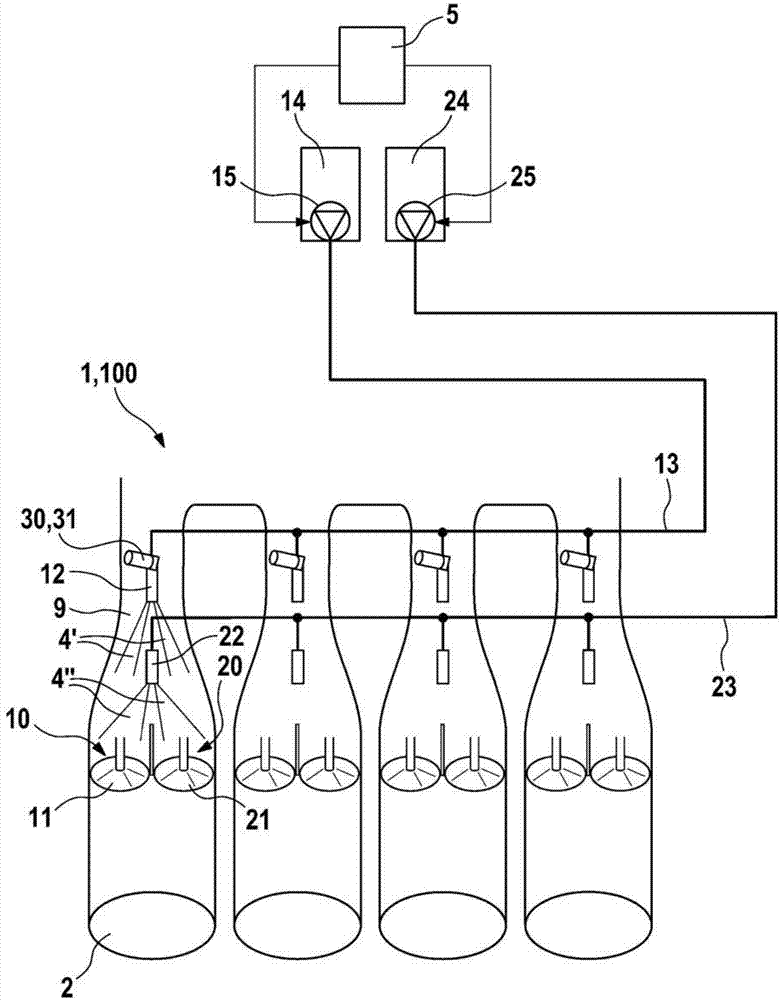
[0018] figure 1 A schematic diagram of an injection device 1 according to an exemplary embodiment of the invention and an internal combustion engine 100 at least partially is shown. The internal combustion engine 100 is depicted with, for example, four cylinders. Each of these four cylinders includes a combustion chamber 2 in which a piston, not shown, moves. The walls of each combustion chamber 2 respectively have a first inlet 10 and a second inlet 20 through which the air-fuel mixture is sucked into the combustion chamber 2 via a suction pipe 9 . Each combustion chamber also has an outlet, not shown, through which untreated exhaust gases of the burned air-fuel mixture exit the combustion chamber 2 . Each cylinder also has a first inlet valve 11 and a second inlet valve 21 , wherein the first inlet valve 11 i...


PUM


Abstract

The invention relates to an injection device (1) for an internal combustion engine (100), comprising a first injection valve (12) for injecting fuel of a first fuel combination based on ethanol, and a separate second injection valve (22) for injecting fuel of a second fuel combination that differs from the fuel combination of the first fuel combination. The injection device (1) is provided with a heating unit (30) for pre-heating exclusively the fuel of the first fuel combination injected by way of the first injection valve (12).

Description

technical field [0001] The invention relates to a spraying device according to the preamble of claim 1 . Background technique [0002] Such injection devices for injecting fuel into internal combustion engines are generally known. For example, from the publication DE 2158117 A1 an internal combustion engine with a throttle adjustment mechanism is known, in which the fuel is injected by means of an injection device into a suction pipe which leads into the combustion chamber of the internal combustion engine, wherein the fuel is injected prior to injection by means of an electric fuel heater Heating to improve the evaporation of fuel after injection. Here, the internal combustion engine is an Otto engine with a straw injection system, which runs on gasoline-based fuel. [0003] Furthermore, it is also known, for example from the publication DE 10 2009 000 894 A1, that internal combustion engines are not only operated with petrol-based fuels, but are also additionally or excl...

Claims


Application Information

Patent Timeline
Patent Type & Authority Applications(China)
IPC IPC(8): F02D19/08F02M31/125F02M35/10F02M43/04F02M53/06F02M69/04F02D41/06F02D41/30
CPCF02D41/064F02D19/0647F02M31/02Y02T10/126F02M43/04F02M31/125F02D19/081F02D19/0692F02D41/0025F02M35/10216F02M69/044F02D19/084F02M53/06Y02T10/12Y02T10/30
Inventor T·温德贝格斯
Owner ROBERT BOSCH GMBH
Why Eureka
Eureka Blog
Learn More