Airtight test device for tube bundles for heat exchangers

A technology of heat exchanger and airtight test, which is applied in the direction of heat exchanger sealing device, heat exchange equipment, heat exchanger type, etc., which can solve the problems of poor economy, large workload, high test cost, etc.

Active Publication Date: 2017-06-30
CHIYODA CORP
View PDF5 Cites 0 Cited by
  • Summary
  • Abstract
  • Description
  • Claims
  • Application Information

AI Technical Summary

Problems solved by technology

[0015] Therefore, in the case of carrying out the airtight test of the tube bundles 2, 14 for various heat exchangers, it is necessary to prepare many main bodies 20 and test rings 21, 62 corresponding to the types in advance, and ensure storage places for these many test rings 21. The cost of the test is high, the economy is poor, and a lot of work is required in the maintenance and management of the main body 20 and the test rings 21 and 62

Method used


Image

  • Airtight test device for tube bundles for heat exchangers
  • Airtight test device for tube bundles for heat exchangers
  • Airtight test device for tube bundles for heat exchangers

Examples


Embodiment Construction

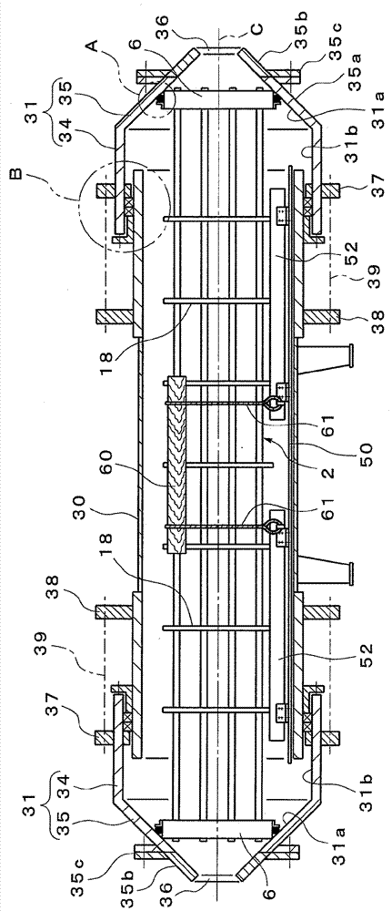
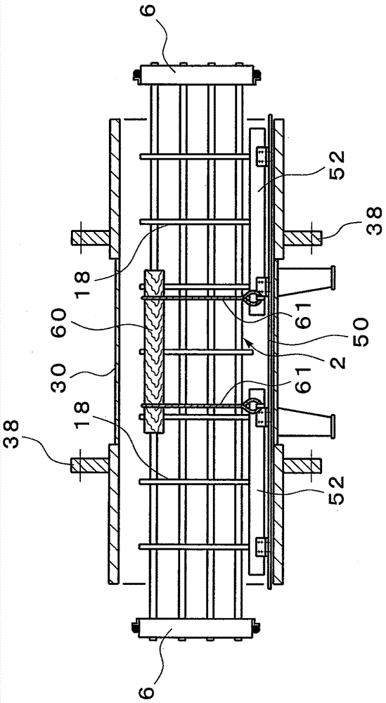
[0037] Figure 1 to Figure 8 Indicates that the airtight test device related to the tube bundle of the present invention is used to carry out Figure 10 A diagram of an embodiment of the airtight test of the tube bundle 2 of the floating head heat exchanger shown, with regard to the structure of the tube bundle 2, and Figure 10 The shown configurations are the same, so the descriptions thereof will be simplified by giving the same reference numerals below.

[0038] First, if Figure 1 to Figure 5 As shown, the airtight test device consists of a cylindrical main body 30, sealing covers 31 respectively arranged at the openings at both ends of the main body 30, the inner surface 31a of the sealing cover 31 and the tube sheet 6 of the tube bundle 2. The O-ring (first sealing member) 32 that airtightly seals between the outer circumference of the body, and the packing gland (second seal) that airtightly seals between the inner surface 31b of the sealing cover 31 and the outer surf...


PUM


Abstract

The invention provides a leak testing apparatus of a tube bundle for a heat exchanger that can conduct leak testing to tube bundles of diversified size through 1 testing apparatus, and can guarantee storage safety with simple maintenance. The leak testing apparatus is economic and comprises a tubular main body (30) that makes a tube plate extrude from an opening on a end side, and the tube bundle (2) for heat exchange is stored therein; a first sealing part (32) that is set on the outer peripheral part of the tube plate (2) to seal closely with the inner surface (31a) of the sealing cover; and a second sealing part (33) that is used to seal the sealing cover (31) closely with the outer surface of the main body (30). The inner surface (31a) of the sealing cover (31) has an inclined plane, and the inclined plane is close to an axis (C) side gradually by getting away fom the main body (30) at the axis direction.

Description

technical field [0001] The present invention relates to an airtightness test transposition of a tube bundle for a heat exchanger for checking the airtightness between a plurality of heat transfer tubes and a tube sheet fixing the ends of these heat transfer tubes. Background technique [0002] Figure 10 It is a figure which shows the conventional floating head type (floating head type) heat exchanger which is 1 type of multi-tube heat exchanger, and the reference numeral 1 in a drawing is a cylindrical case. [0003] The casing 1 accommodates a tube bundle for heat exchange (hereinafter simply referred to as a tube bundle) 2 , one end is closed by a cover 3 , and a header 4 is provided at the other end. [0004] The tube bundle 2 is a structure in which a plurality of heat transfer tubes (only two of which are shown in the figure) 5 are arranged in parallel at predetermined intervals, and a plurality of baffles ( (not shown in the figure) is positioned and fixed to the dis...

Claims


Application Information

Patent Timeline
Patent Type & Authority Patents(China)
IPC IPC(8): G01M3/04
CPCF28D7/06F28D7/16F28F9/0248F28F2230/00G01M3/14
Inventor 广冈丰治米山久男
Owner CHIYODA CORP
Why Eureka
Try Eureka