
Single image fast phase shift system and phase detection method based on deflection angle

A single image, deflection angle technology, applied in the direction of measurement devices, measurement optics, optical radiation measurement, etc., can solve the problem that speckle cannot achieve rapid deformation measurement, etc.

Inactive Publication Date: 2016-03-30
HEFEI UNIV OF TECH
View PDF4 Cites 2 Cited by
  • Summary
  • Abstract
  • Description
  • Claims
  • Application Information

AI Technical Summary

Problems solved by technology

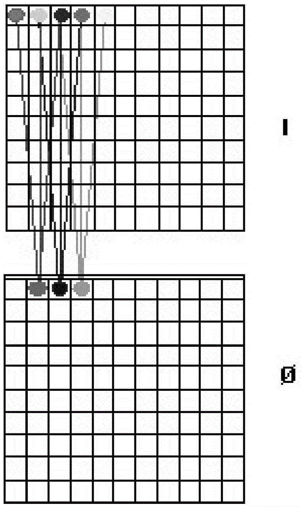
[0014] The technical problem to be solved by the present invention is to avoid the deficiencies in the above-mentioned prior art, provide a single image fast phase shift system and phase detection method based on the deflection angle, and adjust the large speckle generated by laser interference, so that It covers many pixels of the CCD array in the spatial domain. Through the phase calculation of a single pixel and its adjacent pixels, it only needs to collect a single image to obtain the phase map of the light field interference, in order to obtain the phase of the speckle under dynamic and fast measurement. information, effectively solving the problem that traditional speckle measurement cannot achieve rapid deformation measurement

Method used


Image

  • Single image fast phase shift system and phase detection method based on deflection angle
  • Single image fast phase shift system and phase detection method based on deflection angle
  • Single image fast phase shift system and phase detection method based on deflection angle

Examples


Embodiment Construction

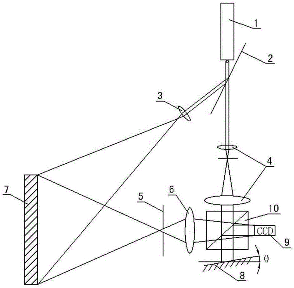
[0041] See figure 1 In this embodiment, the system configuration of the single image rapid phase shift system based on the deflection angle includes a laser 1, a variable nd filter 2, a beam expander 3, a collimating component 4, an aperture stop 5, an imaging lens 6, Reflecting mirror 8, dichroic prism 10 and CCD camera 9.

[0042] In this embodiment, the output light of the laser 1 is divided into object light and reference light by the variable nd filter 2. The object light is expanded by the beam expander 3 and then irradiated to the surface of the object 7 to form laser speckle interference. The return object light on the surface of the measured object is projected on the target surface array of the CCD camera 9 through the aperture stop 5 and the imaging lens 6 in turn; the reference light is collimated by the collimating component 4 into a reference collimated laser with a larger aperture diameter. The collimated laser is irradiated on the target surface array of the CCD ...


PUM


Abstract

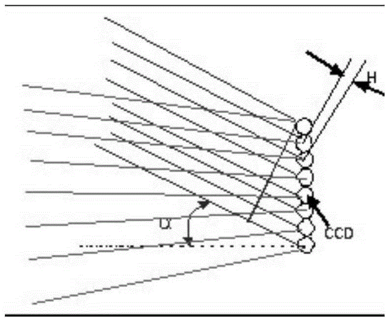
The invention discloses a single image rapid phase displacement system and method based on deflection angles. The system and method are characterized in that object light emitted by a laser device irradiates an object surface to be detected to form laser speckle interference, and return object light from the object surface to be detected irradiates a target surface array of a CCD camera; reference light emitted by the laser device irradiates the target surface array of the CCD camera at an angle alpha through a collimation component and a reflector, and generates a laser interference phenomenon on the target surface array of the CCD camera together with return object light, the angle alpha is adjusted, a 120-degree optical path difference exists between reference light of two adjacent pixel points, and the phase value of the laser interference phenomenon is calculated according to the numerical values of three adjacent pixel points in information recorded by the CCD camera. By means of the single image rapid phase displacement system and method, only a single image is used in speckle interference so that rapid phase detection can be achieved, and a PZT displacement micro-movement system required by the time phase displacement method does not need to be used.

Description

Technical field [0001] The invention relates to a speckle interferometry system and a phase detection method, especially an optical fast phase shift method, which can be widely used in the measurement of strain and deformation in various aspects such as mechanical manufacturing, aerospace, materials and biology, and can realize rapid displacement Field, deformation field, vibration field detection, and non-destructive non-contact measurement of materials, frames and components. Background technique [0002] Digital SpecklePatternInterferometry (DSPI) is a photometric method that integrates laser, electronics, and image processing technologies. It has the advantages of high precision, non-contact and full-field measurement. Therefore, it is widely used in the measurement of machinery manufacturing, aerospace, materials and biology. [0003] Figure 4 For the existing speckle interferometry system based on time phase shift, the laser light emitted by the laser 101 is divided into two...

Claims


Application Information

Patent Timeline
Patent Type & Authority Patents(China)
IPC IPC(8): G01B11/16G01J9/02
Inventor 王永红孙建飞杨连祥
Owner HEFEI UNIV OF TECH
Learn More