
Drying device in high-speed rough drawing production line

A drying device and production line technology, applied in drying, drying machine, progressive dryer and other directions, can solve the problems of long drying box length and large area, and achieve short drying box length and occupying space. Small area, good drying effect

Inactive Publication Date: 2014-04-09
柳城县鼎铭金属制品有限公司
View PDF7 Cites 5 Cited by
  • Summary
  • Abstract
  • Description
  • Claims
  • Application Information

AI Technical Summary

Problems solved by technology

[0003] The invention provides a drying device for a high-speed rough drawing production line, which can solve the problems of long drying boxes and large occupied areas of the existing drying device

Method used


Image

  • Drying device in high-speed rough drawing production line
  • Drying device in high-speed rough drawing production line

Examples


Embodiment Construction

[0008] Below in conjunction with accompanying drawing example, the present invention is described in further detail:

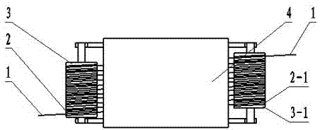
[0009] Such as figure 1 The shown embodiment includes wire rod 1, wire groove 2, wire groove 2-1, feeding drum 3, feeding drum 3-1, drying box 4.

[0010] exist figure 1 , figure 2 The feeding drums 3 and 3-1 shown in the figure are respectively provided with wire slots 2 distributed in a spiral shape. The spiral wire groove 2 of the material drum 3 and the spiral wire groove 2-1 of the feeding drum 3-1 at the discharge end pass back and forth through the drying box 4 and finally from the spiral wire groove of the feed drum 3-1 at the discharge end. The end of the wire duct 2-1 is output to the next process of the production line. Since the wire 1 passes through the drying box 4 multiple times back and forth, the residence time of the wire 1 in the drying box 4 is ensured, and the drying effect is good.


PUM


Abstract

The invention discloses a drying device in a high-speed rough drawing production line. The drying device comprises a drying box and conveying rollers arranged at the charge end and discharge end of the drying box, wherein spirally-distributed wire guide grooves are formed in the conveying rollers respectively; wires penetrate through the drying box back and forth along the spirally-distributed wire guide grooves of the conveying rollers at the charge end and discharge end of the drying box, and are finally output from the tail ends of the spirally-distributed wire guide grooves of the conveying roller at the discharge end. Compared with the prior art, according to the drying device, the problems of long length and large floor area of the drying box of the existing drying device in a rough drawing production line can be solved.

Description

technical field [0001] The invention relates to the technical field of metal product production, in particular to a drying device for a high-speed rough drawing production line. Background technique [0002] The drying device of the existing high-speed rough drawing production line includes a drying box, a feeding roller arranged at the feeding end of the drying box and a feeding roller at the discharging end, and the wire is fed into the drying box after being output from the continuous wire drawing machine. The feeding roller at the end of the drying box enters the drying box, and then is sent out from the feeding roller at the discharge end of the drying box to enter the next process. The wire rod of this structure of the drying device only passes through the drying box once, so the drying box The length must be extended to ensure that the wire stays in the drying box for a good drying effect, but in the actual high-speed rough drawing production line, in order to shorte...

Claims


Application Information

Patent Timeline
Patent Type & Authority Applications(China)
IPC IPC(8): F26B13/10F26B25/00
Inventor 张瑞杰
Owner 柳城县鼎铭金属制品有限公司
Learn More