
Novel controllable telescopic rod

A telescopic rod, a new type of technology, applied in the connection of rods, connecting components, mechanical equipment, etc., can solve the problems of return error, limiting the application scope of the telescopic mechanism, and limited application scope.

Inactive Publication Date: 2014-04-09
周帅
View PDF0 Cites 11 Cited by
  • Summary
  • Abstract
  • Description
  • Claims
  • Application Information

AI Technical Summary

Problems solved by technology

[0003] However, the existing telescopic methods generally have the following deficiencies: the hydraulic cylinder needs hydraulic pipelines and control valves to form a complete hydraulic system, which has a complex structure, takes up a large space, and has limited application range; the screw mechanism needs to control the forward and reverse rotation of the motor to drive The screw mechanism is connected with the load to achieve expansion and contraction, and the expansion and contraction speed is slow; the rack and pinion mechanism requires the motor to drive the gear to rotate in the forward and reverse directions, so as to drive the rack and the load to achieve linear reciprocating motion, thereby realizing the expansion and contraction of the rod. The expansion and contraction length is discontinuous, and Backlash error caused by gear backlash
However, none of the above telescopic methods can achieve flexible switching between internal drive and external drive, which largely limits the scope of application of the telescopic mechanism.

Method used


Image

  • Novel controllable telescopic rod
  • Novel controllable telescopic rod
  • Novel controllable telescopic rod

Examples


Embodiment Construction

[0014] Below we further elaborate on the telescopic rod of the patent of the present invention in combination with the accompanying drawings, in order to explain the structure and use method of the new telescopic rod more clearly.

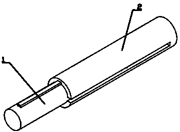
[0015] Such as figure 1 As shown, the telescopic rod part 1 of the novel controllable telescopic rod is nested on the telescopic rod part 2, and can slide and stretch.

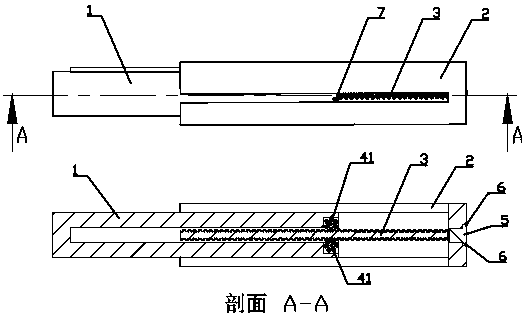
[0016] Such as figure 2 As shown, the spherical roller turntable 41 is connected with the telescopic rod 1 through the shaft 43 , the motor 5 is fixed on the telescopic rod 2 through the positioning screw 6 , and the output shaft of the motor is connected with the worm cam 3 . The worm cam 3 cooperates with the spherical roller turntable 41. When internally driven, the spherical roller turntable 4 is locked, and the motor 5 drives the worm cam 3 to rotate, so that the worm cam 3 and the telescopic rod 2 can move back and forth, so that the telescopic rod The part 1 and the teles...


PUM


Abstract

The invention discloses a novel controllable telescopic rod which structurally comprises two sections of hollow telescopic rods, a worm cam, a spherical roller rotating disc, a locking gear, a shaft, a motor, a locating screw and a locking rack switch. The two sections of hollow telescopic rods are nested with each other, the spherical roller rotating disc is arranged on one section of rod through the rotating shaft, the motor is fixed to the other section of rod through the locating screw, and an output shaft of the motor is connected with a worm cam matched with the spherical roller rotating disc. The spherical roller rotating disc is fixedly connected with the locking gear, and the locking rack switch locks the spherical roller rotating disc by being meshed with the locking gear. During internal driving, the spherical roller rotating disc is locked, and the motor drives the worm cam to rotate. During external driving, the spherical roller rotating disc freely rotates, and the worm cam and the spherical roller rotating disc achieve similar movement of the rack and the gear. The novel controllable telescopic rod smoothly extends and retracts, is flexibly and accurately controlled, can achieve switching of internal driving and external driving, and is wide in application range.

Description

technical field [0001] The patent of the present invention relates to a telescopic rod with switchable drive mode, which can realize flexible switching between internal drive and external drive. Background technique [0002] Telescopic rods are widely used in daily life, and are mostly used in clothes drying rods, curtain rods, support rods, mechanical arms and other devices. The common driving telescopic methods include hydraulic cylinder, screw mechanism, rack and pinion mechanism, etc. [0003] However, the existing telescopic methods generally have the following deficiencies: the hydraulic cylinder needs hydraulic pipelines and control valves to form a complete hydraulic system, which has a complex structure, takes up a large space, and has limited application range; the screw mechanism needs to control the forward and reverse rotation of the motor to drive The screw mechanism is connected with the load to achieve expansion and contraction, and the expansion and contrac...

Claims


Application Information

Patent Timeline
IPC IPC(8): F16B7/10
Inventor 虞超周帅曾素颖徐兵乐赞
Owner 周帅
Learn More