
Design principle and manufacturing method of porous material having dynamic adsorption and transfer functions

A technology of porous materials and transfer function, applied in the field of porous materials

Inactive Publication Date: 2014-04-09
POLYU RES BASE SHENZHEN
View PDF11 Cites 13 Cited by
  • Summary
  • Abstract
  • Description
  • Claims
  • Application Information

AI Technical Summary

Problems solved by technology

[0006] Existing technologies have extensively studied the transmission of sweat and rain in clothing fabrics, but these studies are limited to a constant mode, that is, the fabrics in these applications only passively provide A carrier that allows water to pass through or prevents water from passing through

Method used

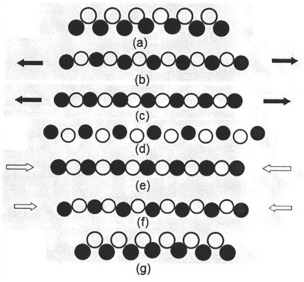

Image

  • Design principle and manufacturing method of porous material having dynamic adsorption and transfer functions
  • Design principle and manufacturing method of porous material having dynamic adsorption and transfer functions
  • Design principle and manufacturing method of porous material having dynamic adsorption and transfer functions

Examples


example 1

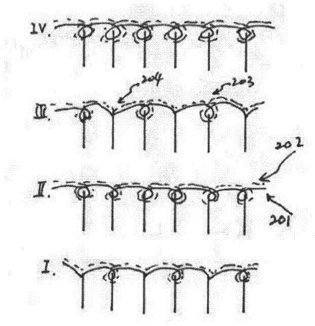
[0028] The fabric in this embodiment is woven by knitting single-side weft knitting technology.

[0029] The fabric structure is a 4-way weaving cycle, and its weaving diagram is as follows figure 2 . The first way: Hydrophobic yarn is tuck-knitted on odd-numbered knitting needles (1, 3,) and tuck-knitted on even-numbered knitting needles (2, 4,). and covered with hydrophobic yarn. The second way: the hydrophilic yarn is woven in a circle on all knitting needles, and the elastic yarn is woven in a circle on all knitting needles at the same time in a single-sided plating method, and is covered by the hydrophilic yarn. The third way: Weave the hydrophobic yarn in a loop on the odd-numbered knitting needles (1, 3,) and weave the hydrophobic yarn in a tuck on the even-numbered knitting needles (2, 4,). and covered with hydrophobic yarn. The fourth way: the weaving method of hydrophilic yarn and elastic yarn is the same as the second way.

[0030] In the weaving cycle, both h...

example 2

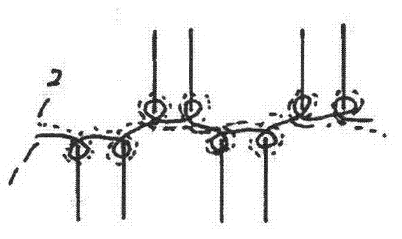
[0033] The fabric in this embodiment is woven by knitting double-sided weft knitting technology ( image 3 ).

[0034] The fabric structure is a double-sided plating structure fabric, and its weaving diagram is shown in the figure. The hydrophobic yarn 1 and the hydrophilic yarn 2 are fed into the same knitting system in the way of plating, so that the yarn 1 covers the yarn 2 when the cylinder knitting needles and dial knitting needles form a loop.

[0035] When the fabric is static, both sides of the fabric are loops of hydrophobic yarns, and when stretched, both sides of the fabric are changed into loops formed by hydrophobic yarns and hydrophilic yarns, which are separated by vertical strips.

example 3

[0037] The fabric in the present embodiment is woven by knitting warp knitting technology ( Figure 4 ).

[0038] The fabric has a 4-comb structure

[0039] GB4 (back comb) is elastic yarn, full wear; GB3 is hydrophobic yarn, full wear; GB2, GB1 are hydrophilic yarns, GB2 2 wear 2 empty, GB13 empty 2 wear 1 empty. The motion diagram of the yarn lapping of the fabric is shown in the figure, and the number of lapping yarns is as follows:

[0040] GB1: 3-2 / 2-3 / 2-1 / 1-2 / 1-0 / 0-1 / 1-2 / 2-1 / 2-3 / 3-2 / 3-4 / 4-3 / 4-5 / 5-4 / 4-3 / 3-4 / /

[0041] GB2: 2-3 / 3-2 / 3-4 / 4-3 / 4-5 / 5-4 / 4-3 / 3-4 / 3-2 / 2-3 / 2-1 / 1-2 / 1-0 / 0-1 / 1-2 / 2-1 / /

[0042] GB3: 1-0 / 1-2 / /

[0043] GB$: 3-4 / 1-0 / /

[0044]In order to confirm the dynamic adsorption and transfer function of the porous material of the present invention, a dynamic moisture content test (MMT tester) was performed on the fabric of Example 1. The fabric is woven by 70D Tactel, 70D p.p and 40DLycra. Figure 5 It is the moisture content of the technical reverse side...


PUM


Abstract

The invention relates to a design principle and a manufacturing method of a porous material having dynamic adsorption and transfer functions, and relates to the porous material which has the functions of dynamically adsorbing and transferring a certain medium according to a certain direction through the fabric structure changes formed in a fabric dimension changing process. According to the technical scheme, the porous fabric is weaved by at least a media-philic material and a media-phobic material so that a stereoscopic layering effect of at least two layers is produced. When the fabric is in a static state, the inner media-phobic material conducts to the surface-layer media-philic material. When the fabric is in a dynamic tensile deformation state, the layer effect converts until the media-philic material converts from the surface layer to the inner layer to directly adsorb a medium. During dynamic deformation recovery, the structure gradually recovers until the media-philic material adsorbing the medium returns from the inner layer back to the surface layer. By repeating the process, the medium is conducted from the inner media-phobic material to the surface-layer media-philic material when the fabric is in the static state, and a large amount of adsorption transfer of the medium is achieved during dynamic deformation.

Description

technical field [0001] The invention relates to a porous material, especially a porous fabric formed by weaving yarns with different surface energy characteristics according to a specific structure. The porous fabric can form a fabric structure during the process of fabric size change change, so that the porous fabric has the function of dynamically absorbing and transferring a certain medium according to the set direction. technical background [0002] With the improvement of living standards, people's requirements for clothing are also constantly improving. In addition to meeting the most basic functions of daily warmth, people are increasingly pursuing wearing comfort. It is mainly reflected in that the clothes should have good moisture absorption and perspiration performance at the same time, otherwise the wearer will feel damp and cold after sweating. Therefore, it is a common goal in the industry to develop a fabric with excellent heat and humidity management. [00...

Claims


Application Information

Patent Timeline
Patent Type & Authority Applications(China)
IPC IPC(8): D06N7/04D06N7/02
Inventor 李翼周金云曹旭勇胡军岩姚磊
Owner POLYU RES BASE SHENZHEN
Learn More