
Air cylinder special for pneumatic compression type oil vapor recovery sealing device of train

A technology of pneumatic pressing and sealing device, which is applied in distribution device, special distribution device, liquid distribution, conveying or transferring device, etc., can solve the problems of insufficient pressing force, insufficient rigidity, insufficient pressing force of sealing device and sealing requirements, etc. , to achieve stable and reliable locking force, reduce overall weight and compact structure

Active Publication Date: 2014-04-09
CHINA PETROLEUM & CHEM CORP QINGDAO RES INST OF SAFETY ENG +1
View PDF7 Cites 2 Cited by
  • Summary
  • Abstract
  • Description
  • Claims
  • Application Information

AI Technical Summary

Problems solved by technology

[0002] At present, the commonly used sealing devices in the field of oil and gas recovery include conical caps or flat caps that rely on outer arms to lock, and Maza-type sealing devices that rely on self-weight or magnetic force sealing. These manual sealing devices not only provide insufficient pressing force, but also cannot completely seal the tank. mouth, and the operation is inconvenient and labor-intensive
There is also an air cylinder on the vertical pipe of the crane tube, relying on the rigidity of the outer arm of the crane tube to press the tank mouth. Although this device can be automated, due to the long outer arm of the crane tube, the rigidity is not enough, and the tanker has subsidence when loading oil. , so it is still not possible to completely seal the mouth of the jar
Insufficient compression force of the above-mentioned sealing device is the main reason why the current sealing device cannot fully meet the sealing requirements, and has become a technical bottleneck for improving the recovery rate of the oil and gas recovery system

Method used


Image

  • Air cylinder special for pneumatic compression type oil vapor recovery sealing device of train

Examples


Embodiment Construction

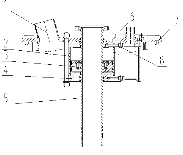
[0009] A special cylinder for a train pneumatic compression type oil and gas recovery sealing device, including a medium flow pipe 5 and a sealing cover 6 matched with the tank opening on the top of the train tank car. The groove is equipped with a rubber gasket 7, and the rubber gasket 7 is provided with a harder dovetail connection part matched with the above-mentioned dovetail groove, in order to connect firmly; a softer sealing part is provided below the dovetail connection part, which can Compensate the flatness error of the tank mouth during sealing to improve the sealing performance; there is an installation hole in the middle of the sealing cover 6 through which the medium flow pipe passes, and an oil and gas recovery port 1 is provided on the sealing cover next to the installation hole, and a The cylinder body 2 is set outside the medium flow pipe 5, the oil and gas recovery port 1 is set on the sealing cover 6 outside the cylinder body 2, and the two ends of the cylin...


PUM


Abstract

The invention provides an air cylinder special for a pneumatic compression type oil vapor recovery sealing device of a train. The air cylinder special for the pneumatic compression type oil vapor recovery sealing device of the train comprises a medium overflowing pipeline and a sealing cover matched with a top tank opening of a train tanker. An annular dovetail groove is formed along the outer edge of the lower surface of the sealing cover. A rubber sealing gasket is arranged at the position of the dovetail groove. The rubber sealing gasket is provided with a hard dovetail connection portion. A soft sealing portion is arranged below the dovetail connection portion. A medium overflowing pipeline installation hole is formed in the center of the sealing cover. A cylinder barrel body is arranged below the sealing cover and the medium overflowing pipeline is sleeved with the cylinder barrel body. A pressure cavity is formed between the outer wall of the medium overflowing pipeline and the inner wall of the cylinder barrel body. A piston is arranged in the pressure cavity. The medium overflowing pipeline is sleeved with the piston and is fixedly connected with the piston. The air cylinder is specially designed and manufactured for the structure of the sealing device and can not only provide stable and reliable locking force but also be integrated with a sealing recovery assembly. The air cylinder is compact in structure, economical, environmentally friendly, capable of greatly reducing the overall weight of the device, and capable of being more conveniently used in cooperation with a loading arm.

Description

technical field [0001] The invention relates to a loading and unloading device for volatile oil products or chemical media, in particular to a special cylinder for a train pneumatic compression type oil gas recovery and sealing device. Background technique [0002] At present, the commonly used sealing devices in the field of oil and gas recovery include conical caps or flat caps that rely on outer arms to lock, and Maza-type sealing devices that rely on self-weight or magnetic force sealing. These manual sealing devices not only provide insufficient pressing force, but also cannot completely seal the tank. mouth, and the operation is inconvenient and labor-intensive. There is also an air cylinder on the vertical pipe of the crane tube, relying on the rigidity of the outer arm of the crane tube to press the tank mouth. Although this device can be automated, due to the long outer arm of the crane tube, the rigidity is not enough, and the tanker has subsidence when loading oil...

Claims


Application Information

Patent Timeline
Patent Type & Authority Applications(China)
IPC IPC(8): B67D7/06
Inventor 吴立峰陈普宽尚庆付卢西林陈福强刘林
Owner CHINA PETROLEUM & CHEM CORP QINGDAO RES INST OF SAFETY ENG
Learn More