
Movable cantilever hoisting device

A lifting device and mobile technology, applied in the direction of portable lifting device, hoisting device, etc., can solve the problems of human health damage, high labor intensity, low efficiency, etc. The effect of restriction

Active Publication Date: 2014-04-09
GUILIN UNIV OF ELECTRONIC TECH
View PDF6 Cites 14 Cited by
  • Summary
  • Abstract
  • Description
  • Claims
  • Application Information

AI Technical Summary

Problems solved by technology

The lifting equipment of the truck-mounted crane is installed on the car, and there must be a place where the car can enter and exit, so its use in a small indoor space is restricted.
Moreover, the purchase of rail cranes and truck-mounted cranes is still a relatively large investment for small businesses.
Although there are various column-type jib cranes with simple structure and low cost, it is inconvenient when lifting materials because the column is fixed.
Although the electric hoist is low in cost, it needs to be equipped with a tripod temporarily when using it, which is not only inconvenient, but also requires a certain amount of installation space
In many cases, small companies and units can only rely on manual handling, which is extremely labor-intensive, harmful to human health, prone to personal accidents, and inefficient

Method used


Image

  • Movable cantilever hoisting device
  • Movable cantilever hoisting device
  • Movable cantilever hoisting device

Examples


Embodiment Construction

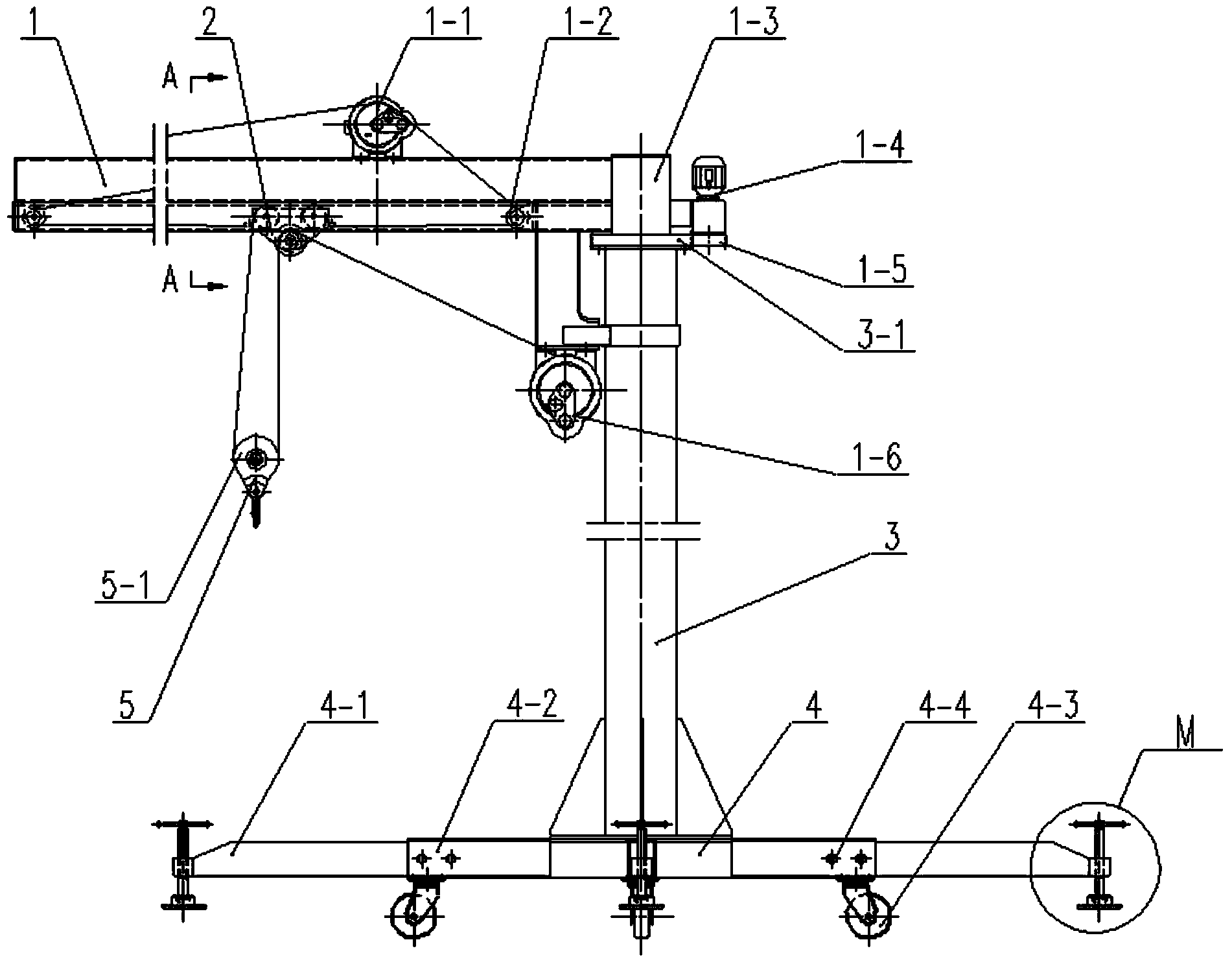
[0024] The overall structure of the embodiment of the mobile cantilever lifting device is as follows: figure 1 Shown is a self-propelled jib hoist equipped with feet.

[0025] The bottom end of the vertical column 3 is fixedly connected to the base 4, the bottom of one end of the beam 1 is vertically fixedly connected to the sleeve 1-3, the top of the column 3 is inserted into the sleeve 1-3, and the other end of the beam 1 extends horizontally as a cantilever. There is a convex ring on the column 3, and the bottom end of the sleeve pipe 1-3 is stuck on the convex ring, and the sleeve pipe 1-3 and the column 3 are dynamic fits. A bull gear 3-1 is fixed on the column 3 below the convex ring. The beam 1 is extended to the tail outside the column 3 to fix the motor 1-4, the output shaft of the motor 1-4 is connected to the reducer, and the drive gear 1-5 is fixed on the output shaft of the reducer, and the drive gear 1-5 meshes with the large gear 3-1 .

[0026] The electric h...


PUM


Abstract

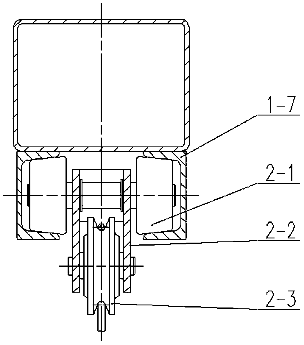
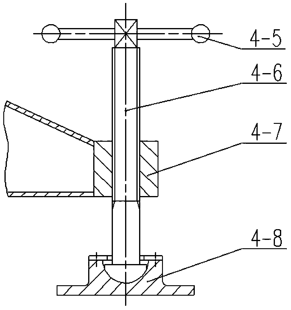
The invention discloses a movable cantilever hoisting device. One end of a transverse beam is installed at the top end of a stand column, and the other end of the transverse beam serves as a cantilever. An electric block is hung below the position, close to the stand column, of the cantilever. A traveling beam formed by box iron with opposite notches is fixedly connected below the transverse beam, the two sides of an n-shaped trolley frame of a pulley trolley are provided with traveling wheels clamped and embedded in the notches of the traveling beam, and a pulley is located between side plates of the trolley frame. A double-rope-outlet electric winch is fixedly installed on the top face of the transverse beam, and two traveling steel wire ropes bypass small fixed pulleys at the two ends of the traveling beam respectively to be fixedly connected to the pulley trolley to pull the pulley trolley to move along the traveling beam. A hoisting steel wire rope of the electric block bypasses the pulley of the pulley trolley to then bypass a movable pulley of a hosting hook to be fixed to the pulley trolley. The top end of the stand column is inserted into a sleeve fixedly connected with one end of the transverse beam, and a driving gear fixed to a motor at the tail of the transverse beam is meshed with a large gear on the stand column to drive the cantilever to rotate. Fixing supporting legs with universal wheels can be installed on a base of the stand column, and can be fixed to an automobile chassis or a cross platform wagon through connectors. The movable cantilever hoisting device is simple in structure and flexible and convenient to use.

Description

technical field [0001] The invention relates to the technical field of hoisting machinery, in particular to a mobile cantilever hoisting device. Background technique [0002] Indoor and outdoor warehouses, workshops, docks, etc., need to frequently move heavy goods such as goods or products, but small enterprises or logistics companies cannot invest in the installation of gantry cranes. Some of these units install rail cranes, and some use truck-mounted cranes, or only Can use electric hoist. [0003] Rail cranes cannot work outside the rails. The lifting equipment of the truck-mounted crane is installed on the car, and there must be a place for the car to enter and exit, which limits its use indoors in a narrow space. Moreover, the purchase of rail cranes and truck-mounted cranes is still a relatively large investment for small businesses. Although there are various column-type jib cranes, the structure is simple and the cost is low, but because the column is fixed, it i...

Claims


Application Information

Patent Timeline
IPC IPC(8): B66D3/18
Inventor 唐海斌宋宜梅周东波刘光辉
Owner GUILIN UNIV OF ELECTRONIC TECH
Learn More