
Jack shear pin removal device and method

A technology of shearing pins and jacks, applied in metal processing, metal processing equipment, manufacturing tools, etc., can solve the problems of loose and broken wire ropes, labor and time-consuming, etc., to reduce manpower, simple and easy to implement dismantling methods, and shorten the replacement and maintenance period Effect

Active Publication Date: 2016-03-02
STATE GRID CORP OF CHINA +1
View PDF4 Cites 0 Cited by
  • Summary
  • Abstract
  • Description
  • Claims
  • Application Information

AI Technical Summary

Problems solved by technology

Due to the limitation of the site and tools, the whole work is laborious and time-consuming, and it needs to be pulled with a bridge crane, which may cause unsafe hazards such as loose wire ropes and broken wires.

Method used


Image

  • Jack shear pin removal device and method
  • Jack shear pin removal device and method

Examples


Embodiment Construction

[0023] The present invention will be further described in detail below in conjunction with specific embodiments, which are explanations of the present invention rather than limitations.

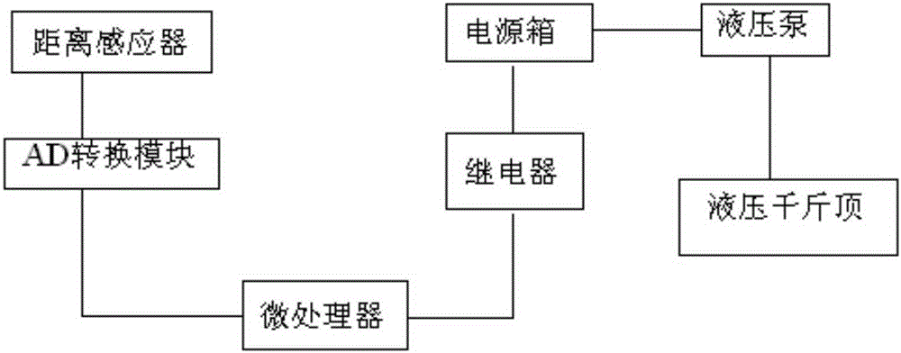
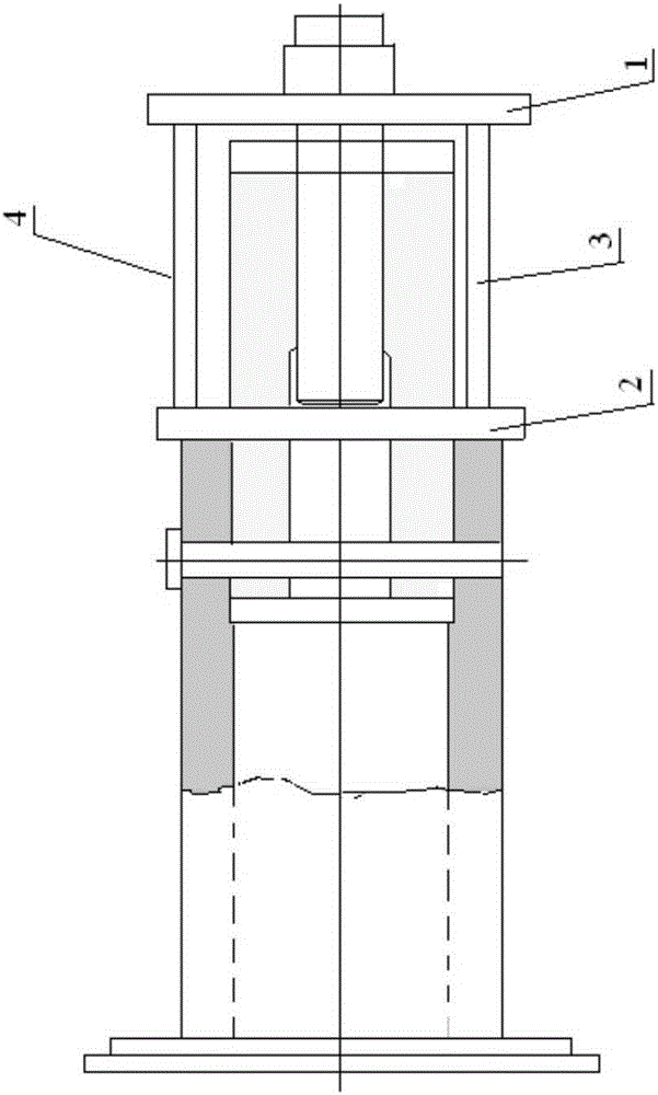
[0024] see figure 1 and figure 2 , the jack shearing pin removal device of the present invention comprises an upper flange 1 and a lower flange 2, a hydraulic jack is arranged between the upper flange 1 and the lower flange 2, and a distance sensor is arranged on the upper flange 1 The distance sensor adopts an infrared distance sensor; the distance sensor is connected with the input terminal of the microprocessor through an AD conversion module, and the output terminal of the microprocessor is connected with the control terminal of the hydraulic jack through a relay. Among them, the microprocessor adopts single-chip microcomputer or DSP.

[0025] Preferably, the hydraulic jack is a thin hydraulic jack, and a first thin hydraulic jack 3 and a second thin hydraulic jack 4 controlled by the ...


PUM


Abstract

The invention discloses a device and a method for dismantling shear pins of jacks. The device for dismantling the shear pins of the jacks comprises an upper flange and a lower flange. Hydraulic jacks are arranged between the upper flange and the lower flange, a distance sensor is arranged on the upper flange and is connected with an input end of a microprocessor by an AD (analog and digital) conversion module, and an output end of the microprocessor is connected with control ends of the hydraulic jacks by relays. The device and the method have the advantages that the device is simple in structure, the shear pins can be safely and efficiently dismantled by the aid of the device and the method, accordingly, equipment safety and personal safety can be guaranteed, and stop and defect elimination time of units can be effectively shortened; the method for dismantling the shear pins of the jacks is simple, safe and effective and is easy to implement, replacement and maintenance construction periods of the shear pins of the jacks of upper frameworks can be shortened, and unnecessary labor and material consumption can be reduced.

Description

technical field [0001] The invention relates to a jack shear pin removal device and method. Background technique [0002] The upper frame of the hydroelectric generator set is located at the upper end of the stator. It consists of a central body and twelve arms and is supported on the inner wall of the machine pit. It is the supporting part for the upper guide bearing of the generator set. The rotor radial unbalanced force on the bearing The magnetic pulling force generated by the air gap of the generator and the generator is transmitted to the inner wall of the machine pit through the frame. Since the structure of the unit belongs to the structure without lower guide bearings, in order to reduce the radial vibration of the generator set, a jack that bears radial force is installed on the outer end of the support arm of the upper frame, and one end of the jack is fixed on the wall of the generator pit. The load of the jack is considered to be 1.5-2 times the total load of t...

Claims


Application Information

Patent Timeline
Patent Type & Authority Patents(China)
IPC IPC(8): B23P19/027
CPCB23P19/025B23P19/027
Inventor 李刚康旭辉赵峰宋洋聂磊陈芬环
Owner STATE GRID CORP OF CHINA
Learn More