A method of making an optical fiber cladding power stripper

An optical fiber cladding and stripper technology, applied in cladding fibers, multi-layer core/cladding fibers, etc., can solve problems such as damage to the fiber, threatening the safe operation of the laser, and rise, so as to reduce the temperature rise pressure and ensure safety. running effect

Active Publication Date: 2016-03-02
武汉虹拓新技术有限责任公司
View PDF5 Cites 0 Cited by
  • Summary
  • Abstract
  • Description
  • Claims
  • Application Information

AI Technical Summary

Problems solved by technology

This method has certain shortcomings: because the refractive index of the material around the fiber cladding in the leakage window area is higher than that of the fiber core, the leaked light will radiate from around the cladding, and the heat generated will cause the temperature here to rise rapidly , especially at one end of the leakage window where the laser first passes through, a high temperature point 04 will be generated, such as image 3 shown
When the leakage power is greater, the temperature of the high temperature point will be higher, which will greatly threaten the safe operation of the laser, and seriously damage the optical fiber

Method used


Image

  • A method of making an optical fiber cladding power stripper
  • A method of making an optical fiber cladding power stripper
  • A method of making an optical fiber cladding power stripper

Examples


Embodiment Construction

[0021] The present invention will be further described below in conjunction with specific examples.

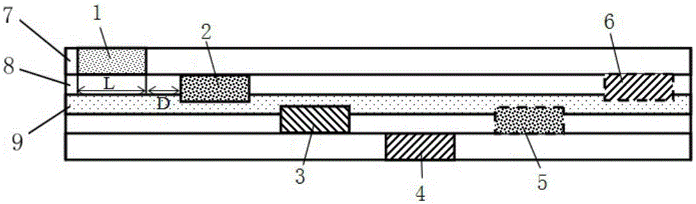
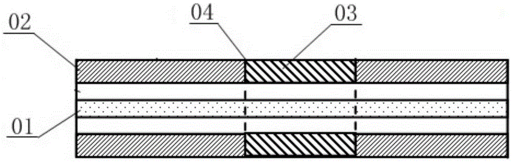
[0022] The method for making the optical fiber cladding power stripper described in this embodiment is to first divide the double-clad optical fiber that needs to be made into a power stripper according to its length direction to have multiple regions; secondly, in the corresponding region, double-clad The low-refractive coating layer on the first-layer optical fiber, that is, the outer cladding, is partially peeled off to obtain the required optical power leakage window nude, and there is a relative rotation angle with the fiber core as the axis between the adjacent optical power leakage window nudes; Finally, the finished bare optical power leakage window is coated and cured with high-refractive index ultraviolet glue, and the power stripper is completed so far. Combine below figure 1 and figure 2 , the inventive method is specified, and its specific circumstances are as...


PUM


Abstract

The invention discloses a method for manufacturing a fiber cladding power stripper. The method comprises the following steps: firstly partitioning a doubly coated fiber which is required for manufacturing a power stripper into multiple region segments along the length direction; then partially stripping low-refraction coatings, namely external coatings, on the doubly coated fiber in the corresponding region segments so as to obtain required light power leakage window naked bodies, wherein relative rotation angles which take a fiber core as an axis exist among the adjacent required light power leakage window naked bodies; finally coating and curing the manufactured light power leakage window naked bodies by use of ultraviolet glue with high refractive index, thereby finishing the manufacturing of the fiber cladding power stripper. According to the method, the coatings on the fiber are partially stripped, multiple light power leakage windows are manufactured in a multi-region multi-angle mode, leaked light power is distributed in multiple regions of the fiber, so that the temperature of an initial leakage point of leaked light is greatly reduced, and the safe operation of devices is ensured.

Description

technical field [0001] The invention relates to the technical field of manufacturing an optical power stripper, in particular to a method for manufacturing an optical fiber cladding power stripper. Background technique [0002] As is known in the industry, fiber lasers and fiber amplifiers have become research hotspots in recent years due to their high conversion efficiency and good stability. In fiber lasers or fiber laser amplifiers, double-clad fibers doped with rare earth impurities are usually used as gain media, where the refractive index of the core is n 1 greater than the refractive index n of the inner cladding 2 , the refractive index n of the inner cladding 2 is greater than the refractive index n of the outer cladding 3 , namely n 1 >n 2 >n 3 . The fiber core serves as the transmission channel of the laser signal light, and the inner cladding serves as the transmission channel of the pump light. When the pump light is transmitted in the fiber, it is...

Claims


Application Information

Patent Timeline
Patent Type & Authority Patents(China)
IPC IPC(8): G02B6/036
Inventor 张凤杰曹祥东崔索超李德荣邓建
Owner 武汉虹拓新技术有限责任公司
Why Eureka
Try Eureka