
Flow field real-time precise measuring system and method

An accurate measurement and flow field technology, applied in fluid velocity measurement, measurement device, velocity/acceleration/impact measurement, etc., which can solve the problems of low measurement accuracy, large error, and inability to respond to the flow field in real time.

Active Publication Date: 2014-04-02
HUAZHONG UNIV OF SCI & TECH
View PDF6 Cites 27 Cited by
  • Summary
  • Abstract
  • Description
  • Claims
  • Application Information

AI Technical Summary

Problems solved by technology

[0004] In view of the above defects or improvement needs of the prior art, the present invention provides a real-time accurate flow field measurement system and method, the purpose of which is to measure the flow field adaptively through time resolution and spatial resolution, thereby solving the current time resolution The flow field measurement system with fixed rate and spatial resolution has low measurement accuracy and large error for the rapidly changing flow field, and cannot respond to the flow field in real time, especially the technical problems of the hypersonic flow field.

Method used


Image

  • Flow field real-time precise measuring system and method
  • Flow field real-time precise measuring system and method
  • Flow field real-time precise measuring system and method

Examples


Embodiment 1

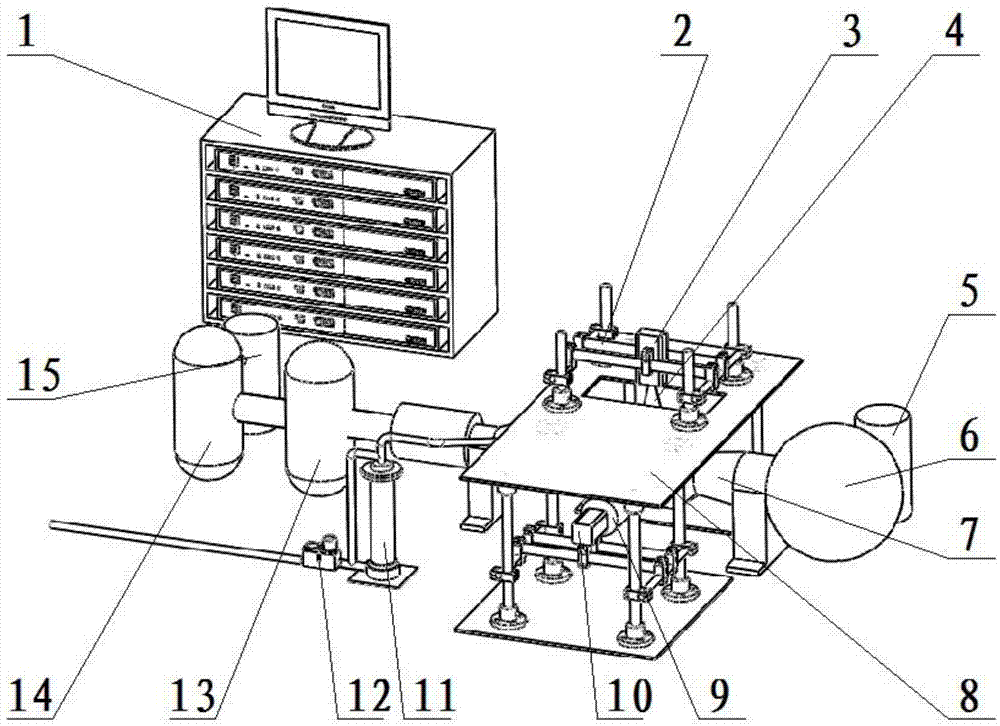
[0110] A field real-time precise measurement system, including: tracer particle generator, image processing subsystem and PIV measurement subsystem, such as figure 1 shown.

[0111] Using a small wind tunnel, a hypersonic flow field is generated for measurement. The production of a small wind tunnel is mainly composed of an air compressor, a purification device, an air storage tank, a vacuum box and a vacuum pump. Among them, the air compressor is used to compress air to form high-pressure air flow; the purification device is used to dehumidify, degrease, and remove impurities in the high-pressure gas in the air compressor to form a pure flow field; the gas storage tank is used to store gas to buffer , to ensure the stable air pressure of the ejected gas; the vacuum box is used to form a stable vacuum negative pressure on one side of the small wind tunnel; the vacuum pump is used to generate vacuum.

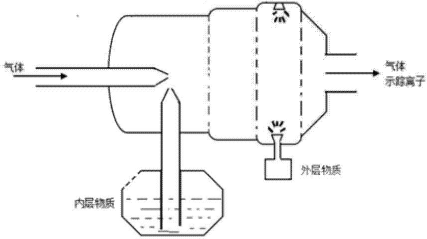
[0112] tracer particle generators such as figure 2 As shown, it is used ...

Embodiment 2

[0120] A real-time accurate measurement method for a flow field, comprising the following steps, wherein the time interval Δt between the image at the first moment and the image at the second moment 1 and query window parameters at the first moment, which are manually specified:

[0121] (1) According to the time interval Δt between the particle image of the longitudinal section of the flow field at time n+1 and the particle image of the longitudinal section of the flow field at time n n , collect the particle image of the longitudinal section of the flow field at the n+1th time, and perform noise reduction processing on the particle images of the longitudinal section of the flow field at the nth time and the n+1th time.

[0122] Noise reduction processing is performed on the particle image of the flow field longitudinal section at the nth time and the flow field longitudinal section particle image at the n+1th time. The noise reduction method can use Gaussian filtering method...

Embodiment 3

[0162] Fill the tracer particles with high dispersion and strong followability in the tracer particle generator, arrange the thin sheet laser light in the image acquisition system along the direction of the flow field, and arrange the image acquisition device perpendicular to the direction of the flow field. Start the tracer particle generator, laser emission unit and ultra-high-speed image acquisition device, like this.

[0163] The laser emitting unit emits sheet laser intermittently to illuminate the tracer particles, and the ultra-high-speed image acquisition device triggers and collects the tracer particle images of the longitudinal section of the flow field at the same time as the laser is emitted, and transmits them to the host computer of the PIV measurement subsystem.

[0164]The upper computer preprocesses and displays the collected images, and then transmits them to the lower computer of the PIV measurement subsystem. The lower computer adjusts the spatial resolution...


PUM


Abstract

The invention provides a flow field real-time precise measuring system and a flow field real-time precise measuring method. The system comprises a tracer particle generator, an image processing sub system and a PIV (particle image velocimetry) measuring sub system, wherein the tracer particle generator is arranged at the upper stream of a flow field to be measured, and the image processing sub system collects tracer particle images in the flow field and transmits the images to the PIV measuring sub system. The method comprises the following steps that the space resolution regulation information and the time resolution regulation information are calculated according to the previous measurement, the inquiry window parameter and the image collection speed are regulated, during the measurement in the last time, the flow field particle images are collected according to the regulated image collection speed, the regulated inquiry window parameters are adopted for the image and the previous image, and the current full flow field vector is obtained through adopting a particle image speed measuring method. The flow field real-time precise measuring system and the flow field real-time precise measuring method provided by the invention have the advantages that the real-time measurement is carried out on the high-flow-speed flow field, particularly the hypersonic flow field and the violently changed flow field, and the precision is high.

Description

technical field [0001] The invention belongs to the field of fluid measurement, and more specifically relates to a real-time and precise measurement system and method for a flow field. Background technique [0002] In the research on the simulation and test of the flow inside the flow field, the previous test methods, such as the probe method and the LDV system, have greatly disturbed the flow field, so that the test results and research conclusions are quite different from the reality. access. [0003] In the field of flow field velocity measurement, especially in the field of hypersonic flow field velocity measurement, accurate fluid dynamics measurement is more important. When an object moving at ultra-high speed encounters an obstacle, complex flow field phenomena such as shock wave, expansion wave, and boundary layer will appear, and its aerodynamic characteristics present the characteristics of ultra-high speed, unsteady, and non-uniform height. Now challenges to the...

Claims


Application Information

Patent Timeline
Patent Type & Authority Applications(China)
IPC IPC(8): G01P5/22
Inventor 杨华尹周平熊有伦梅爽钟强龙张步阳李勇
Owner HUAZHONG UNIV OF SCI & TECH
Learn More