Optical interferometer for detecting outer arc surface of annular guide rail

An annular guide rail and optical interference technology, applied in the field of optical interferometers, can solve the problems of the influence of interferometer detection accuracy and reliability, detection profile deviation, and inability to obtain three-dimensional surface profile at one time, so as to improve test efficiency and precision. , the effect of improving accuracy and reliability, and improving test efficiency

Inactive Publication Date: 2014-04-02
苏州慧利仪器有限责任公司 +2
View PDF9 Cites 8 Cited by
  • Summary
  • Abstract
  • Description
  • Claims
  • Application Information

AI Technical Summary

Problems solved by technology

[0003] However, existing interferometers often detect deviations in surface shape, such as curved or partially curved or concave-convex areas. For the detection of three-dimensional surface shape, repeated inspections are required, and all three-dimensional surface shapes cannot be obtained at one time; secondly, The detection accuracy and reliability of existing interferometers are easily affected by environmental factors such as external vibration, temperature, and airflow

Method used


Image

  • Optical interferometer for detecting outer arc surface of annular guide rail
  • Optical interferometer for detecting outer arc surface of annular guide rail
  • Optical interferometer for detecting outer arc surface of annular guide rail

Examples


Embodiment 1~3

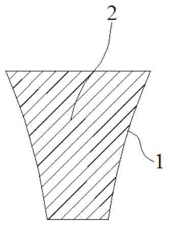
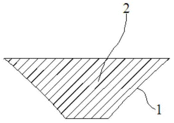
[0026] Embodiments 1~3: An optical interferometer for detecting the outer arc surface of a ring rail. The outer arc surface 1 is located along the circumferential direction of the ring rail 2 and is located outside, including a laser 3, a condenser lens 4, and a beam splitter The lens 5, the collimating convex lens 6, the reference lens 7 and the annular bevel mirror 8 as the objective lens, the condensing convex lens 4 is located between the laser 3 and the collimating convex lens 6 and the focal point of the condensing convex lens 4 is the same as that of the collimating convex lens 6. The focal point coincides; the beam splitter 5 is located between the condenser convex lens 4 and the collimating convex lens 6, and is used to divide the light from the collimating convex lens 6 into a first beam and a second beam; the reference lens 7 is located in the collimator The side of the convex lens 6 opposite to the beam splitter 5, the surface of the reference lens 7 opposite to the ...


PUM


Abstract

The invention discloses an optical interferometer for detecting the outer arc surface of an annular guide rail. A condenser convex lens is positioned between a laser and a collimating convex lens, and the focus of the condenser convex lens is coincided with the focus of the collimating convex lens. A beam splitter is positioned between the condenser convex lens and the collimating convex lens and is used for dividing a light ray from the collimating convex lens into a first light beam and a second light beam, the surface, which is opposite to the collimating convex lens, of a reference lens is a convex surface, and the surface, which is back-to-back with the convex surface, of the reference lens is a standard reference surface; an annular reflecting slope which is arranged in the middle of an annular slope reflector is arranged in the peripheral direction and is arranged on the inner side, the annular guide rail to be detected is positioned in the annular slope reflector, a rotating axle of the annular slope reflector is coincided with the respective axes of the annular guide rail and the reference lens, and the annular guide rail is arranged outside the focus of the reference lens. All the stereoscopic appearance information of the outer arc surface of the annular guide rail can be obtained in a one-time manner, and meanwhile, the test efficiency, accuracy and reliability are greatly improved.

Description

Technical field [0001] The invention relates to an optical detection device, in particular to an optical interferometer for detecting the outer arc surface of an annular guide rail. Background technique [0002] Optical interference technology is one of the most precise and effective testing technologies in modern times. It integrates the latest contemporary technology and widely adopts the latest achievements in computer technology, laser technology, electronic technology, semiconductor technology and other fields. It can quickly and accurately complete optical parts Check with the system. In today’s optical workshop, from the design, processing and inspection of optical parts to the assembly, calibration and testing of optical systems, the interferometer has become an indispensable test and inspection device that is easy to operate, reliable, high-precision, and intelligent. It plays an important role in the mass production and inspection of optical parts and systems. [0003] ...

Claims


Application Information

Patent Timeline
Patent Type & Authority Applications(China)
IPC IPC(8): G01B9/02G01B11/24
Inventor 韩森李雪园孙昊
Owner 苏州慧利仪器有限责任公司
Why Eureka
Try Eureka