Door lock device and DC power distribution cabinet for communication using the device

A technology for power distribution cabinets and door locks, which is applied in substation/power distribution device shells, building locks, buildings, etc. It can solve the problem of fast opening of door locks, difficulty in realizing rapid opening, and difficulty in ensuring reliable connection between cabinet doors and cabinet bodies, etc. problem, to achieve the effect of simple structure

Active Publication Date: 2017-02-15
GUANGDONG ZHICHENG CHAMPION GROUP
View PDF8 Cites 0 Cited by
  • Summary
  • Abstract
  • Description
  • Claims
  • Application Information

AI Technical Summary

Problems solved by technology

From the perspective of preventing accidental opening of the cabinet door and preventing the cabinet door from being opened by accidental impact, the door lock should have strong fastening strength, and because the cabinet body is usually high, it is difficult to lock the cabinet body and the cabinet door through a single position. Ensure the reliable connection between the cabinet door and the cabinet body; and from the perspective of emergency handling of emergencies, it is difficult to quickly open the door lock with multiple locks
[0004] In order to improve the fastening strength of the existing power distribution cabinet door locks, multiple separate door locks are provided between the door body and the cabinet. Although this structure can ensure the strength of the door locks to each part of the power distribution cabinet, the When opening the door, it is necessary to open each door lock one by one, and it is difficult to open quickly

Method used


Image

  • Door lock device and DC power distribution cabinet for communication using the device
  • Door lock device and DC power distribution cabinet for communication using the device
  • Door lock device and DC power distribution cabinet for communication using the device

Examples


Embodiment 1

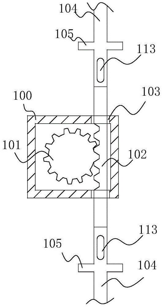
[0038] Such as Figure 1~5 As shown, in this embodiment, a door lock device according to the present invention includes a fixed locking device and a motion locking device that cooperate with each other to realize the locking function. The circular lock cylinder 101 that rotates in the lock housing 100 under the drive of the drive, the lock housing 100 is provided with the operation hole, and the control handle stretches out to the outside of the lock housing 100 through the operation hole.

[0039] The outer surface of the lock cylinder 101 is provided with a gear structure, and one side of the lock cylinder 101 is vertically provided with a rack 102 that matches the gear structure on the outer surface of the lock cylinder 101. A guide groove is provided in the lock housing 100, and the rack 102 is arranged In the guide groove and can slide in the guide groove under the action of the lock cylinder 101 , a relief hole 103 is provided on the lock case 100 to allow the rack to pa...

Embodiment 2

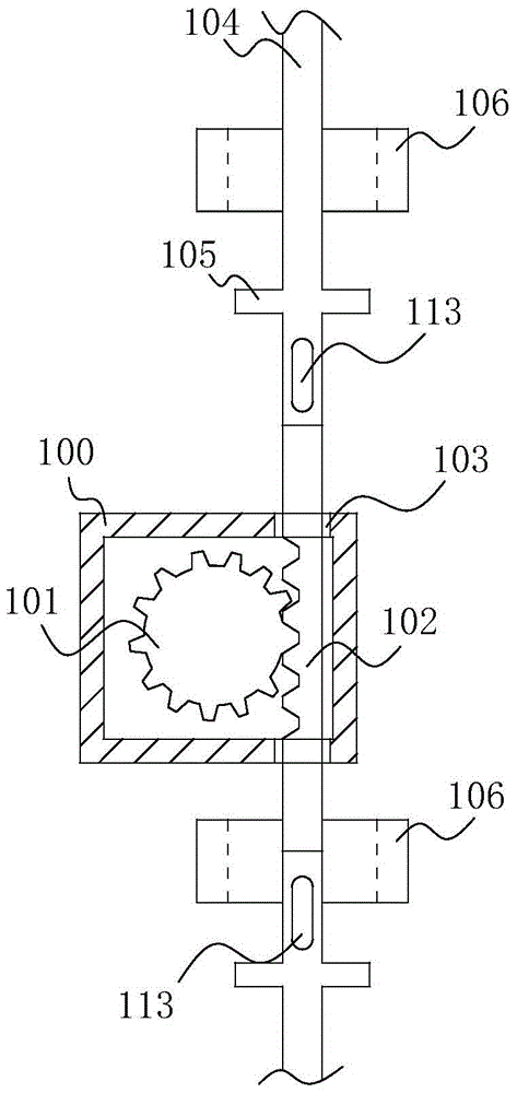
[0046] Such as Figure 6As shown, the structure of the door lock device in this embodiment is basically the same as that of the door lock device in Embodiment 1. The difference is that this embodiment has a first rack 202 and a second rack 203, and the first rack 202 and the second rack The two racks 203 are respectively located on both sides of the lock cylinder 201, the upper surface of the lock housing 200 is provided with a first relief hole 204 through which the first rack 202 can pass, and the lower surface of the lock housing 200 is provided with a first relief hole 204 capable of allowing the The second relief hole 205 through which the second rack 203 passes is fixedly provided with a first interlocking lock bar 206 at one end where the first tooth bar 202 passes through the first relief hole 204 , and the second tooth bar 203 passes through the first relief hole 204 . One end of the second relief hole 205 is fixedly provided with a second interlocking locking bar 207...

Embodiment 3

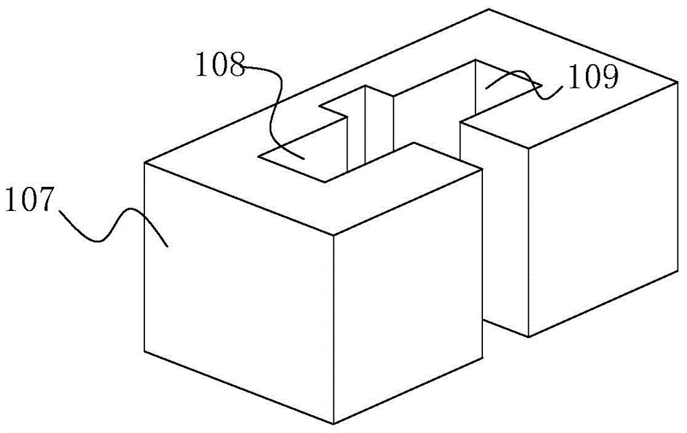
[0049] Such as Figure 7 , 8 As shown, the structures of the lock cylinder 301, the lock case 300, the first rack 302 and the second rack 303 in this embodiment are the same as those in Embodiment 2, the main difference is that the lock cylinder 301 is provided with a The rotating block 304 that can rotate together with the lock core 301, and the fixed block 305 is arranged corresponding to the rotating block 304; The direction is provided with a fixed locking piece 308, and a locking hole that allows the first interlocking locking bar 306 and the second interlocking locking bar 307 to pass through is arranged on the fixed locking piece 308. Driven by the lock cylinder 301, the first linkage When the locking bar 306 and the second interlocking locking bar 307 move to both ends, they respectively pass through the locking holes on the fixed locking piece 308 at the end, and the first interlocking locking bar 306 and the second interlocking locking bar 306 are limited by the fix...


PUM


Abstract

The invention discloses a door locking device which comprises a lock cylinder, a control handle, linkage lock bars and a plurality of fixed locking parts. The lock cylinder can rotate under the control of the control handle and is matched with the linkage lock bars to drive the linkage lock bars to move, a plurality of movable locking parts are arranged on each linkage lock bar, the movable locking parts and the linkage lock bars can move synchronously, the quantity of the movable locking parts is identical to the quantity of the fixed locking parts, the movable locking parts correspond to the fixed locking parts, a rotary block piece is arranged on the lock cylinder, a fixed barrier corresponds to the rotary block piece, the movable locking parts are matched with the fixed locking parts, and the rotary block piece is matched with the fixed barrier, so that the door locking device can be locked. The invention further discloses a direct-current communication power supply distribution box with the door locking device. The door locking device and the direct-current communication power supply distribution box have the advantages that the door locking device is simple in structure and has linkage, multipoint locking and multipoint unlocking functions, and the power supply distribution box can be assuredly reliably locked and can be assuredly quickly opened after the door locking device is arranged in the power supply distribution box.

Description

technical field [0001] The invention relates to the technical field of communication power distribution, in particular to a door lock device and a DC power distribution cabinet for communication using the device. Background technique [0002] The Internet data center is based on the Internet, providing operation and maintenance facilities and related services for centralized collection, storage, processing and sending of data equipment. With the increasingly widespread application, its importance has gradually emerged. In order to ensure the normal operation of the Internet data center, it has high requirements for its power distribution system. In the existing Internet data center computer rooms, AC and DC power distribution cabinets are mostly used for communication power supply. It supplies power, and at the same time provides real-time monitoring of various operating parameters, fault alarms, etc. [0003] In order to ensure the safety of power supply, the door of the p...

Claims


Application Information

Patent Timeline
Patent Type & Authority Patents(China)
IPC IPC(8): E05B65/52E05B63/14H02B1/26
Inventor 舒召林吕培专
Owner GUANGDONG ZHICHENG CHAMPION GROUP
Why Eureka
Try Eureka