
Roof structure of sandblasting room

A technology of sandblasting and driving mechanism, applied in the direction of roof, building components, building structure, etc., can solve the problems of large span, complicated design and installation, and heavy load of flexible gates, achieve simple and direct transmission route, improve hoisting efficiency, improve The effect of blasting efficiency

Active Publication Date: 2014-04-02
常州钢构建设工程有限公司
View PDF8 Cites 3 Cited by
  • Summary
  • Abstract
  • Description
  • Claims
  • Application Information

AI Technical Summary

Problems solved by technology

[0002] The traditional steel structure sandblasting operation is generally carried out in the open air or in an independent sandblasting room. The open air operation and the open roof are greatly affected by the weather, and the ambient temperature and humidity cannot meet the relevant technical requirements. A lot of noise and dust are generated during the process, polluting the environment, and there are many disadvantages; the newly built independent sandblasting room puts forward high requirements for hoisting large components into and out of the sandblasting room. , set up a special flexible gate, the flexible gate has a large span and a heavy load, and a track that slides up and down along the gable column is set. The design and installation are complicated, and the supporting canopy and safety passage must also be designed. Heavy, high cost; portal frame color steel plate roof, in order to prevent the impact of sand on the roof, the lower layer of the roof needs to be covered with hanging steel plates, the structure of the roof system is complex, and the cost of construction and maintenance is also high

Method used


Image

  • Roof structure of sandblasting room
  • Roof structure of sandblasting room
  • Roof structure of sandblasting room

Examples


Embodiment Construction

[0018] The present invention will be described in further detail below in conjunction with the accompanying drawings.

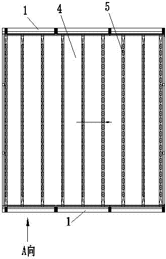
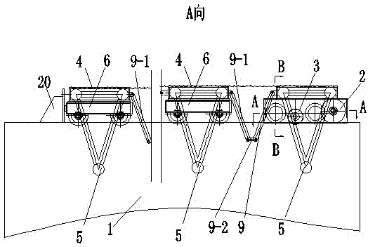
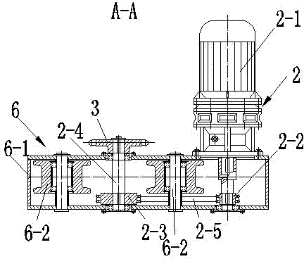
[0019] like Figure 1~6 As shown, a roof structure of a sandblasting room includes a wall 1, a driving mechanism 2, a transmission sprocket 3, a flexible tarpaulin 4, several trusses 5, several trolleys 6, sliding rails 7, chains Type track 8 and hinge mechanism 9, sliding track 7 and chain track 8 are fixedly connected on the top of wall body 1, drive mechanism 2 and drive sprocket wheel 3 transmission connections, and all are fixedly connected on the first trolley 6, finally A trolley 6 is provided with a limit fixing plate 20, and the transmission sprocket 3 is engaged with the chain track 8 for transmission. Through the transmission connection of the hinge mechanism 9, the trolley 6 is connected with the sliding track 7 in a rolling manner, and the flexible tarpaulin 4 is fixedly connected with several trusses 5 .

[0020] see image 3 As shown, in ord...


PUM


Abstract

The invention discloses a roof structure of a sandblasting room. The roof structure of the sandblasting room comprises a wall body and also comprises a driving mechanism, a transmission chain wheel, a flexible tarpaulin, a plurality of trusses, a plurality of trolleys, a sliding rail, a chain rail and a hinge structure; the sliding rail and the chain rail are fixedly connected onto the upper portion of the wall body; the driving mechanism is in transmission connection with the transmission chain wheel; the driving mechanism and the transmission chain wheel are fixedly connected onto the first trolley; the transmission chain wheel is meshed with the chain rail in a transmission mode; two ends of the plurality of trusses are fixedly connected with the corresponding trolleys respectively; the plurality of trusses are hinged to each other through the hinge structure; the trolleys are in rolling connection with the sliding rail; the flexible tarpaulin is fixedly connected with the plurality of trusses. According to the roof structure of the sandblasting room, the sealing effect is good, the pollution to the external environment in the process of sandblasting is avoided, and the efficiency and the quality of the sandblasting are improved.

Description

technical field [0001] The invention relates to a flexible and openable sandblasting house roof system, which is especially suitable for the sandblasting house roof system for building steel structures. Background technique [0002] The traditional steel structure sandblasting operation is generally carried out outdoors or in an independent sandblasting room. The outdoor operation is open and the roof is open. It is greatly affected by the weather, and the ambient temperature and humidity cannot meet the relevant technical requirements. A lot of noise and dust are generated during the process, polluting the environment, and there are many disadvantages; the newly built independent sandblasting room puts forward high requirements for hoisting large components into and out of the sandblasting room. , set up a special flexible gate, the flexible gate has a large span and a heavy load, and a track that slides up and down along the gable column is set. The design and installation...

Claims


Application Information

Patent Timeline
Patent Type & Authority Applications(China)
IPC IPC(8): E04B7/16
Inventor 蔡小平周芊陈晓亮李祥
Owner 常州钢构建设工程有限公司
Learn More