Hydraulic brick conveying machine

A technology of brick transportation and hydraulic pressure, which is applied in the field of brick manufacturing, can solve the problems of low yield of bricks, achieve high adjustable performance, reduce costs, and reduce unsafe factors

Active Publication Date: 2014-04-02
王强
View PDF5 Cites 0 Cited by
  • Summary
  • Abstract
  • Description
  • Claims
  • Application Information

AI Technical Summary

Problems solved by technology

[0004] In order to overcome the deficiencies of the prior art above, the present invention provides a hydraulic brick transporter, the purpose of which is to solve the problem of low yield of bricks during the transportation and storage of bricks during maintenance

Method used


Image

  • Hydraulic brick conveying machine

Examples


Embodiment Construction

[0012] In order to deepen the understanding of the present invention, the present invention will be further described below in conjunction with the accompanying drawings and embodiments, which are only used to explain the present invention and do not limit the protection scope of the present invention.

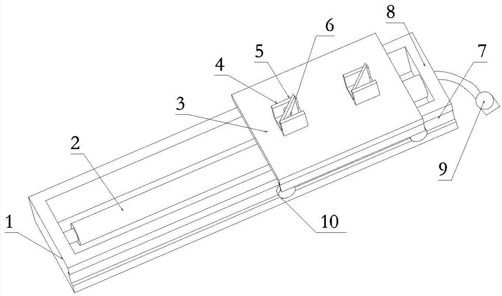
[0013] Such as figure 1 As shown, a hydraulic brick conveyor includes a guide rail 1 arranged on the ground. The guide rail 1 includes two beams 8 and two rails 7. The two rails 7 are parallel, and the two beams 8 are connected to the two rails 7 At the end, the brick conveyor also includes a hydraulic shaft 2, a slide plate 3, and a hydraulic pump 9. The hydraulic shaft 2 is connected to the two beams 8 in the middle of the guide rail 1, the slide plate 3 is connected to slide above the guide rail 1, and the hydraulic pump 9 is connected to the hydraulic shaft. 2. At one end, the hydraulic pump 9 drives the hydraulic shaft 2 to move, thereby driving the slide plate 3 to move ...


PUM


Abstract

The invention discloses a hydraulic brick conveying machine. The hydraulic brick conveying machine comprises a guide rail arranged on the ground, a hydraulic shaft, a sliding plate and a hydraulic pump, wherein the guide rail comprises two cross beams and two rails; the two rails are parallel to each other; the two cross beams are connected with the two ends of the rails; the hydraulic shaft is connected with the two cross beams in the middle of the guide rail; the sliding plate is connected above the guide rail and slides above the guide rail; the hydraulic pump is at one end of the hydraulic shaft; the hydraulic pump drives the hydraulic shaft to move so as to drive the sliding plate to move along the guide rail to convey bricks. The hydraulic power source adopted by the hydraulic brick conveying machine has high adjustable performance, and the conveying of bricks with great weight can be born; the hydraulic brick conveying machine has higher practical performance compared with an electric brick conveying machine, and can be not limited by using place and time, the brick conveying efficiency is improved, unsafe factors of workers when the bricks are conveyed are reduced, the yield of the bricks after being sintered is improved, and the sintering cost of the bricks is reduced.

Description

technical field [0001] The invention relates to the technical field of brick manufacturing, in particular to a hydraulic brick transporting machine. Background technique [0002] At present, the sintered bricks need to be placed in the brick kiln for maintenance for a period of time, so that the sintered bricks are stronger. Blocks are directly shoveled to the brick kiln, so that manual labor can be reduced. [0003] However, due to the uneven ground of the construction site, the forklift will shake during the process of transporting from the shoveling position to the brick kiln, resulting in irregular bricks on the forklift, and these irregular bricks will produce voids when entering the brick kiln , and the empty bricks entering the brick kiln are difficult to adjust due to space constraints. On the one hand, the empty bricks are unevenly stressed, which will lead to poor quality of later bricks. On the other hand, if the empty bricks are too large Large, it will have a ...

Claims


Application Information

Patent Timeline
Patent Type & Authority Applications(China)
IPC IPC(8): B65G35/00
Inventor 王强
Owner 王强
Why Eureka
Try Eureka