Environmental-protection dust remover of boiler

A technology for dust collectors and boilers, applied in chemical instruments and methods, dispersed particle separation, combined devices, etc., can solve the problems of affecting the operation effect and efficiency of boilers, easy to block dust removal guide plates, low dust removal efficiency, etc., to improve the mixing effect. , reduce water content, improve the effect of dust removal

Inactive Publication Date: 2014-04-02
大连旅顺锅炉有限公司
View PDF8 Cites 1 Cited by
  • Summary
  • Abstract
  • Description
  • Claims
  • Application Information

AI Technical Summary

Problems solved by technology

Existing boiler dust collectors are mainly divided into ceramic multi-tube cyclone dust collectors, wet desulfurization dust collectors, cloth bag dust collectors and electrostatic precipitators, and the latter two are mainly used by large-scale power station boilers. my country's current industrial boilers are mainly the former two, However, the ceramic multi-tube dust collector can only achieve the dust removal effect and cannot remove the sulfur in the flue gas, so it has basically been eliminated. Therefore, the existing industrial boilers in my country are mainly wet desulfurization dust collectors. The existing wet desulfurization The dust collector is composed of four parts: air inlet, dust removal guide plate, dehydration plate and air outlet, and a spray device can be installed between the air inlet and dust removal guide plate to improve the dust removal efficiency. The dust removal efficiency is low when the spray device is installed, and the dust removal guide plate is easy to be blocked after the spray device is installed, and the failure rate is high during use, which affects the operation effect and efficiency of the boiler. Usage requirements

Method used


Image

  • Environmental-protection dust remover of boiler

Examples


specific Embodiment approach

[0008] detailed description Next, the present invention will be described in detail in conjunction with the accompanying drawings

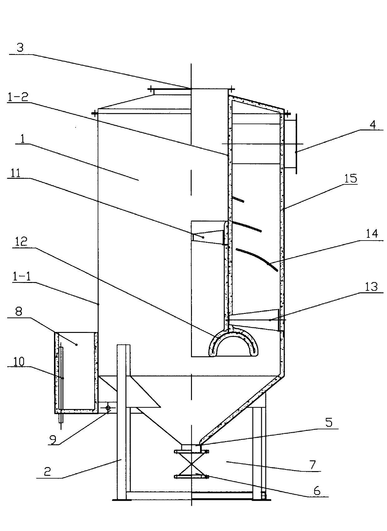
[0009] Such as figure 1 As shown, the bottom of the dust removal chamber 1 is supported by the base frame 2 welded thereto. The dust removal chamber is composed of two hollow shells, that is, an outer shell 1-1 and an inner shell 1-2. The inner shells are both open, the upper end wall of the inner shell is welded with the inner top wall of the outer shell, the top of the outer shell is provided with a smoke inlet pipe 3 communicating with the inner shell, and the side of the outer shell is provided with a smoke outlet pipe communicating with the inside 4. The lower part of the shell is provided with an ash discharge port 5, and a valve 6 is provided at the ash discharge port; the bottom of the shell is provided with an ash cleaning tank 7 corresponding to the ash discharge port, and the ash cleaning tank is a groove-shaped shell with an upp...


PUM


Abstract

The invention relates to an environmental dust remover of a boiler. The top of an outer housing of a dust removing chamber is provided with a fume inlet pipeline which is communicated with an inner housing, and the lateral part of the outer housing is provided with a fume outlet pipeline which is communicated with the inner of the outer housing; the bottom of the outer housing is provided with a dust discharging opening provided with a valve; a dusting cleaning pool corresponding to the dust discharging opening is arranged below the outer housing, the outer lateral wall of the outer housing is welded with a water tank, and the water tank is communicated with the inner part of the outer housing by a water inlet with a valve. The inner part of the inner housing is provided with a whirlwind dust remover close to the middle part, a whirlwind dewaterer is arranged between the inner part of the inner housing and the outer housing, close to the bottom, and the inner wall of the outer housing is welded with a cambered water guide board, which is arranged above the whirlwind dust remover. Compared with the prior art, the dust remover has the advantages of dust removing, high desulphurization efficiency, little water content of flue gas, no influence on the operating effect of the boiler, and the like.

Description

technical field [0001] The invention relates to a dust removal device, in particular to a boiler dust collector. Background technique [0002] The boiler dust collector is an essential part of the coal-fired boiler system. Because of its functions of dust removal and desulfurization, it has always been an indispensable part of the boiler operation system. Existing boiler dust collectors are mainly divided into ceramic multi-tube cyclone dust collectors, wet desulfurization dust collectors, cloth bag dust collectors and electrostatic precipitators, and the latter two are mainly used by large-scale power station boilers. The current industrial boilers in China are mainly the former two. However, the ceramic multi-tube dust collector can only achieve the dust removal effect and cannot remove the sulfur in the flue gas, so it has basically been eliminated. Therefore, the existing industrial boilers in China are mainly wet desulfurization dust collectors, and the existing wet des...

Claims


Application Information

Patent Timeline
IPC IPC(8): B01D50/00B01D53/00
Inventor 佟成伟
Owner 大连旅顺锅炉有限公司
Why Eureka
Try Eureka