Capsule production line system

A production line and capsule technology, which is applied in the field of capsule production line system, can solve the problems of complex structure, reduce the service life of equipment, increase the cost of capsule manufacturing, etc., and achieve the effect of simple structure and uniform oiling

Inactive Publication Date: 2015-05-13
DANDONG JINWAN GRP
View PDF7 Cites 1 Cited by
  • Summary
  • Abstract
  • Description
  • Claims
  • Application Information

AI Technical Summary

Problems solved by technology

Due to the addition of a set of automatic machines and transmission links, first, the structure is relatively complicated; second, the preparation cost of the capsule production line is increased; third, when the capsule production line is running at high speed, the service life of the equipment is reduced; fourth, when the production line is running at high speed, the The power and viscosity requirements of the glue material used to make capsules are relatively high, which relatively increases the manufacturing cost of capsules

Method used


Image

  • Capsule production line system
  • Capsule production line system
  • Capsule production line system

Examples


Embodiment

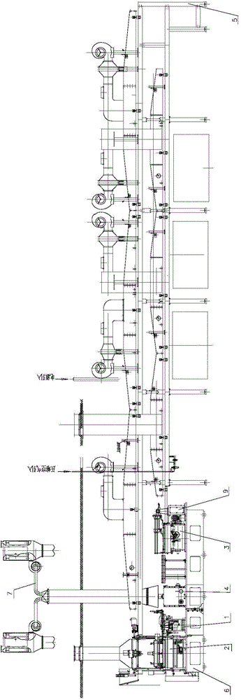
[0091] Example: such as figure 1 As shown, the present invention includes a main base 6, an oiling machine 1, a glue dipping machine 2, an automatic machine 4, a platform machine 3, a conveying drying device, a tail platform lifting mechanism 5 arranged at the end of the conveying drying device, The waste suction device 7 above the automatic machine 4, the large and small conveyor belt devices 16, 15, and the main motor transmission box 9 placed on the oil spreader 1;

[0092] The oiling machine 1, the glue dipping machine 2, the automatic machine 4 and the platform machine 3 are arranged in parallel on the main base 6, respectively connected to the servo motors, and driven by the servo motors;

[0093] The platform machine 3 is installed between the carriage slide 515 and the automatic machine 4 under the conveying drying device, at the end of the main base 6, the main motor transmission box 9 is connected to the platform machine 3 to drive the operation of the platform machine 3;...

Embodiment 2

[0146] Embodiment 2: The difference between this embodiment and embodiment 1 is: Picture 11 , Picture 12 As shown, the transmission device 22 in the glue dipping machine 2 includes a box body 2203, third and fourth gears 2208, 2209, an in-situ trigger ring 2210, and an in-place trigger ring 2211 that are placed in the box 2203 and mesh with each other. The third gear 2208 is mounted on the push-out motor shaft, and the fourth gear 2209 is mounted on the active push-out shaft 5 that extends into the transmission box 2203. The fourth gear 2209 has a sleeve structure. An in-situ trigger ring 2210 is installed at the end of the active push-out shaft 25, and an in-place trigger ring 2211 is installed on the sleeve of the fourth gear 2209; the active push-out shaft 25 rotates to the trigger position of the in-place trigger ring, and the push-out motor 201 reverses and returns to the active position. The ejection shaft 25 rotates to the trigger position of the home position trigger r...


PUM


Abstract

The invention relates to a capsule production system production line and belongs to the technical field of capsule production lines. The capsule production system production line comprises a mainframe base, a glue dipping machine, an oiling machine, an automat, a platform machine, a conveying drying device, a tail platform lifting mechanism, a waste material absorbing device, a large conveying belt device, a small conveying belt device and a main motor transmission case. The glue dipping machine, the oiling machine, the automat and the platform machine are arranged on the mainframe base side by side, the platform machine is installed between a lower pulling plate slideway of the conveying drying device and the automat, the main motor transmission case is connected with the platform machine, a T-shaped slide rail track is arranged between the automat and the platform machine, the glue dipping machine is respectively connected with an upper pulling plate slideway of the conveying drying device and a T-shaped sliding rail of the oiling machine, a platform machine pushing mechanism pushes die strips to respectively slide along a T-shaped sliding rail of the automat and the T-shaped sliding rail of the oiling machine and pushes the die strips having undergoing oiling to the glue dipping machine, and the die strips are dried through the conveying drying device and conveyed to the platform machine, are subject to capsule cutting and capsule peeling through the automat and are synthesized into integral capsules to be output. The capsule production system production line is driven by a servo motor, automatic production in the whole line is achieved, and the efficiency is high.

Description

Technical field [0001] The invention belongs to the technical field of capsule production lines, and particularly relates to a capsule production line system. Background technique [0002] In the capsule production line, all include oiling machine, glue dipping machine, platform machine, automatic machine and drying device. Among them, the mould strips are generally mould strips with single or double rows of mould needles. The number of mould needles in each row is 30, and the production efficiency is low. [0003] The utility model patent with the patent number 2006200325541.9 discloses a single-row die double-head hard capsule production line. It is through adding a set of automatic machines to redesign the working curve of the demoulding cam and the head lifting cam in the automatic machine, and change The transmission ratio of the main drive and the automatic machine increases the operating speed of the capsule production line and achieves the goal of improving production effi...

Claims


Application Information

Patent Timeline
Patent Type & Authority Patents(China)
IPC IPC(8): A61J3/07
Inventor 贾毅周德发朱光耀何福银栾国利庞煜磊周鹏飞唐欣刘金丹
Owner DANDONG JINWAN GRP
Why Eureka
Try Eureka