Mowing machine
A lawn mower and grass feeding technology, applied in the directions of harvesters, cutters, agricultural machinery and implements, etc., can solve the problems of low efficiency, complex and inflexible structure of lawn mowers, etc., so as to achieve a small occupied space and a simple and compact structure. , Easy to operate and flexible effect
- Summary
- Abstract
- Description
- Claims
- Application Information
AI Technical Summary
Problems solved by technology
Method used
Image
Examples
Embodiment 1
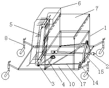
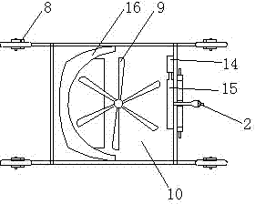
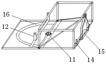
[0022] Embodiment 1: as Figure 1-7 As shown, a lawn mower includes a suspension support frame 1, a power transmission device 2, a bevel gear 3, a belt I 4, a grass feeding device 5, a grass transport tube 6, a grass storage box 7, a universal wheel 8, and a mowing Blade 9, cover plate 10, base flange 11, lower support frame 12, grass tooth slit 13, blower fan 14, air supply channel 15, grass retaining plate 16, belt II 17; the lower end of the suspension support frame 1 and The cover plate 10 is fixedly connected, the crossbeam in the middle of the suspension support frame 1 is provided with a base flange piece 11, one end of the power transmission device 2 is fixed on the suspension support frame 1, and the lower end of the output shaft of the power transmission device 2 passes through the base flange piece 11 It is connected with the rotating shaft of the mowing blade 9, and the rotating shaft of the mowing blade 9 passes through the cover plate 10 and is connected with the...
Embodiment 2
[0023] Embodiment 2: as Figure 1-7 As shown, a lawn mower includes a suspension support frame 1, a power transmission device 2, a bevel gear 3, a belt I 4, a grass feeding device 5, a grass transport tube 6, a grass storage box 7, a universal wheel 8, and a mowing Blade 9, cover plate 10, base flange 11, lower support frame 12, grass tooth slit 13, blower fan 14, air supply channel 15, grass retaining plate 16, belt II 17; the lower end of the suspension support frame 1 and The cover plate 10 is fixedly connected, the crossbeam in the middle of the suspension support frame 1 is provided with a base flange piece 11, one end of the power transmission device 2 is fixed on the suspension support frame 1, and the lower end of the output shaft of the power transmission device 2 passes through the base flange piece 11 It is connected with the rotating shaft of the mowing blade 9, and the rotating shaft of the mowing blade 9 passes through the cover plate 10 and is connected with the...
Embodiment 3
[0025] Embodiment 3: as Figure 1-7 As shown, a lawn mower includes a suspension support frame 1, a power transmission device 2, a bevel gear 3, a belt I 4, a grass feeding device 5, a grass transport tube 6, a grass storage box 7, a universal wheel 8, and a mowing Blade 9, cover plate 10, base flange 11, lower support frame 12, grass tooth slit 13, blower fan 14, air supply channel 15, grass retaining plate 16, belt II 17; the lower end of the suspension support frame 1 and The cover plate 10 is fixedly connected, the crossbeam in the middle of the suspension support frame 1 is provided with a base flange piece 11, one end of the power transmission device 2 is fixed on the suspension support frame 1, and the lower end of the output shaft of the power transmission device 2 passes through the base flange piece 11 It is connected with the rotating shaft of the mowing blade 9, and the rotating shaft of the mowing blade 9 passes through the cover plate 10 and is connected with the...
PUM
 Abstract
Description
Claims
Application Information
 - R&D
- Intellectual Property
- Life Sciences
- Materials
- Tech Scout
- Unparalleled Data Quality
- Higher Quality Content
- 60% Fewer Hallucinations
Browse by: Latest US Patents, China's latest patents, Technical Efficacy Thesaurus, Application Domain, Technology Topic, Popular Technical Reports.
© 2025 PatSnap. All rights reserved.Legal|Privacy policy|Modern Slavery Act Transparency Statement|Sitemap|About US| Contact US: help@patsnap.com


