Portable trolley speaker

A portable, rod-pulling technology, applied in the transducer shell/cabinet/stand, etc., can solve the problems of inconvenient dragging, breaking, inconvenient use and operation, etc., and achieve the effect of convenient transportation and carrying, large bearing capacity, and easy handling.

Active Publication Date: 2018-08-10
NINGBO TONWEL AUDIO
View PDF5 Cites 0 Cited by
  • Summary
  • Abstract
  • Description
  • Claims
  • Application Information

AI Technical Summary

Problems solved by technology

It is time-consuming and labor-intensive to carry the speakers during site layout, and in most cases on the site, it is not suitable to use some means of transportation. The internal structure of the speaker itself includes some metal plates, which are heavy, which will cause a lot of inconvenience when using and operating.
[0003] In order to solve the above problems, according to the prior art, a retractable pull rod is generally provided on the back of the speaker and protrudes from the back or in the middle, but the pull rod is located on the back of the speaker and protrudes from the back. When the pull rod is pulled out and drags the speaker, The pull rod will bear a lot of weight. During the dragging process, the pull rod is easily deformed or even broken, so the load-bearing capacity of the pull rod is small; although the pull rod has a large load-bearing capacity in the middle of the speaker, when the speaker is dragged, the speaker is easy. It is very inconvenient to drag when it hits the person's heel
[0004] In addition, the speaker is generally equipped with a storage cavity for placing microphones and other items. According to the prior art, a drawer-type storage cavity is generally provided on one side of the speaker, and the other side of the storage cavity is a high-frequency In this way, when the size of the cabinet remains the same, the setting of the storage cavity makes the depth of the high-frequency speaker too small, and the sound quality of the high-frequency speaker is poor.

Method used


Image

  • Portable trolley speaker
  • Portable trolley speaker
  • Portable trolley speaker

Examples


Embodiment Construction

[0022] The present invention will be described in further detail below in conjunction with the accompanying drawings and specific embodiments.

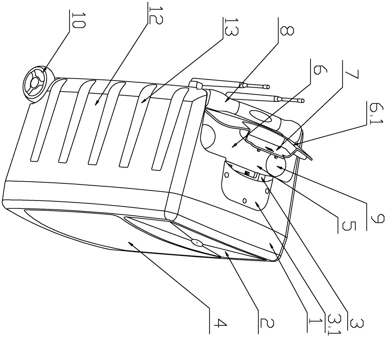
[0023] As shown in the figure, the portable trolley sound box of the present invention includes a front box body 1, a rear box body 12, a power amplifier arranged in the back box body 12 and a tweeter 2 arranged on the top of the front box body 1 and the rear box body 12 , the outlet of the high-frequency loudspeaker 2 is far away from the rear box 12, and the rear side of the rear box 12 is provided with a retractable pull rod 8 and is located in the rear box 1. The bottom of the pull rod 8 is The bottom of the rear box body 12 is provided with a roller 10, and it also includes a first groove 3 which is located on the rear box body 12 and above the high frequency speaker 2 and is connected with the first groove 3 and is close to the pull rod and is deeper than the first groove 3. The deep second groove 6 of the groove 3, the top plat...


PUM


Abstract

The invention discloses a portable pull rod loudspeaker box. The portable pull rod loudspeaker box comprises a front box body (1), a rear box body (12), a power amplifier arranged in the rear box body (12) and a high-frequency speaker (2) arranged at the upper portions of the front box body (1) and the rear box body (12), wherein an outlet of the high-frequency speaker (2) is away from the rear box body (12), a telescopic pull rod (8) is arranged in the rear side of the rear box body (12) and located in the front box body (1), and rolling wheels (10) are arranged at the bottom of the rear box body (12) under the pull rod (8). The portable pull rod loudspeaker box further comprises a first groove (3) arranged in the rear box body (12) and located above the high-frequency speaker (2) and a second groove (6) connected with the first groove (3) and close to the pull rod (8), wherein the second groove (6) is deeper than the first groove (3). The portable pull rod loudspeaker box is large in pull rod bearing capacity and convenient to drag, and the moderate depth of the high-frequency speaker can be ensured, so that the quality of sound made by the portable pull rod loudspeaker box is good.

Description

technical field [0001] The invention relates to a sound box, in particular to a portable trolley sound box. Background technique [0002] Speakers are widely used in various occasions in the entertainment media industry, especially in some large venues and concerts. It is laborious and time-consuming to carry the speakers during the site layout, and in most cases on the site, it is not suitable to use some means of transportation. The internal structure of the speakers itself includes some metal plates, which are heavy, which will cause a lot of inconvenience during use and operation. [0003] In order to solve the above problems, according to the prior art, a retractable pull rod is generally provided on the back of the speaker and protrudes from the back or in the middle, but the pull rod is located on the back of the speaker and protrudes from the back. When the pull rod is pulled out and drags the speaker, The pull rod will bear a lot of weight. During the dragging proc...

Claims


Application Information

Patent Timeline
Patent Type & Authority Patents(China)
IPC IPC(8): H04R1/02
Inventor 闫峻徐益先
Owner NINGBO TONWEL AUDIO
Why Eureka
Try Eureka