
Motor, fly-back control method of motor and energy circulation control method of motor

A technology of energy circulation and control method, applied in the direction of AC motor control, control system, motor generator/starter, etc., can solve problems such as energy consumption, and achieve the effect of reducing iron consumption and saving iron consumption.

Active Publication Date: 2014-03-26
宁德市犇田动力有限公司
View PDF4 Cites 2 Cited by
  • Summary
  • Abstract
  • Description
  • Claims
  • Application Information

AI Technical Summary

Problems solved by technology

Because the result of this is the continuous input of energy, there is no process of storing energy and flyback, resulting in continuous energy consumption

Method used

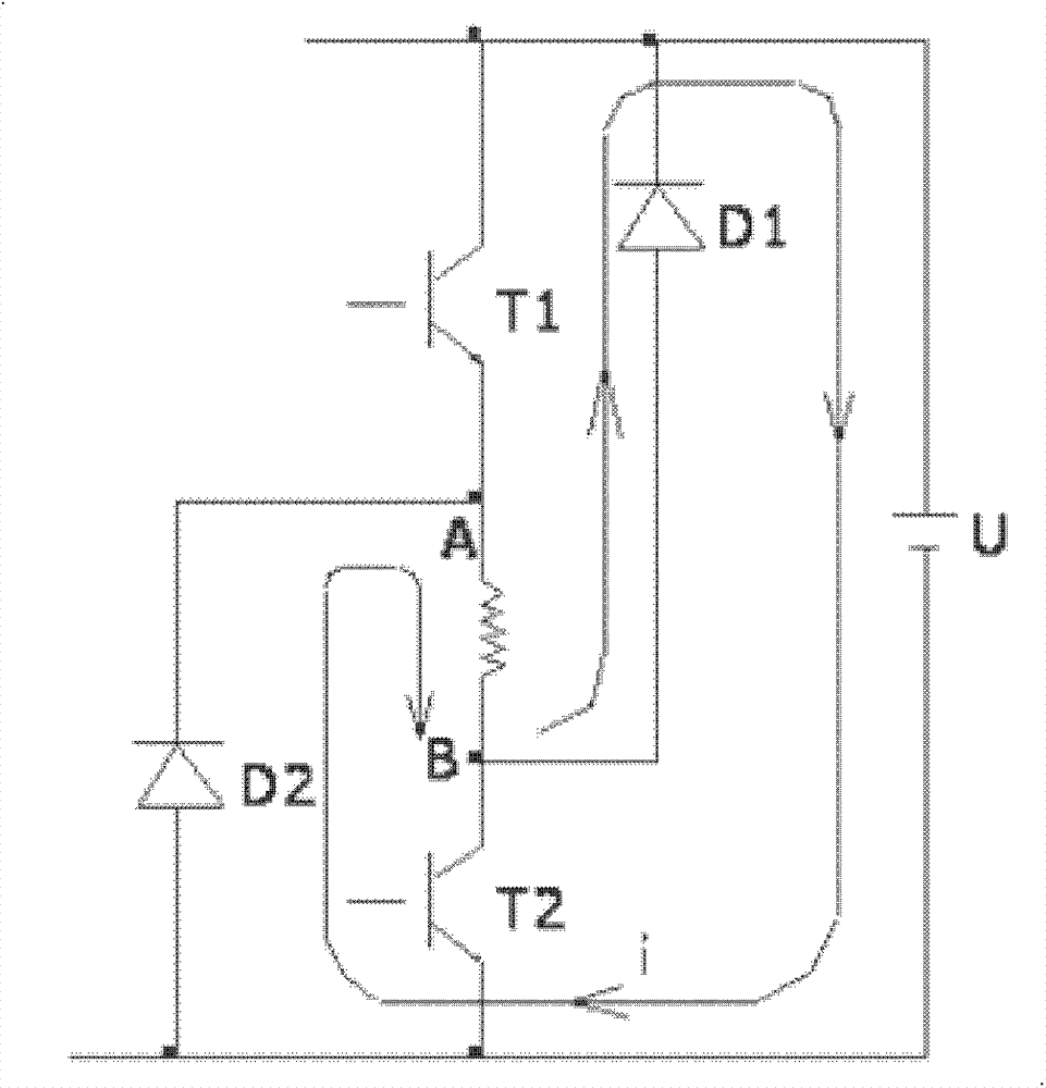
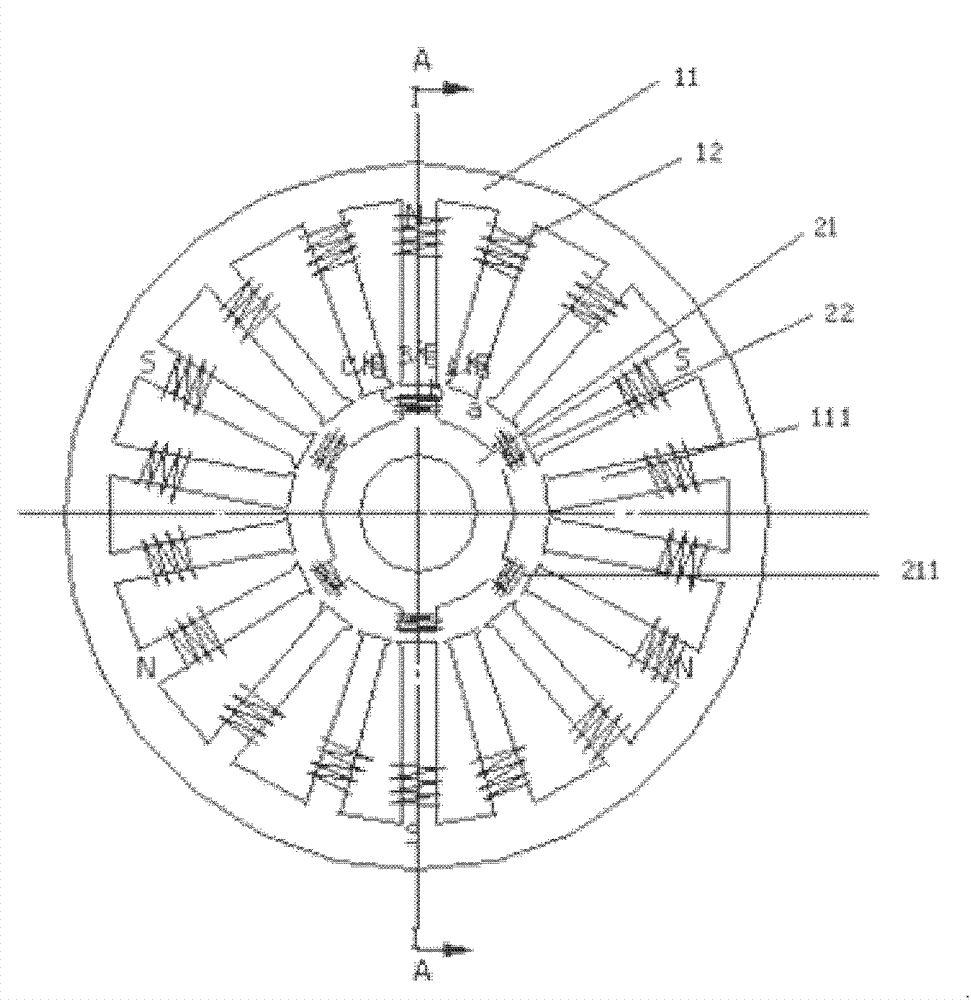
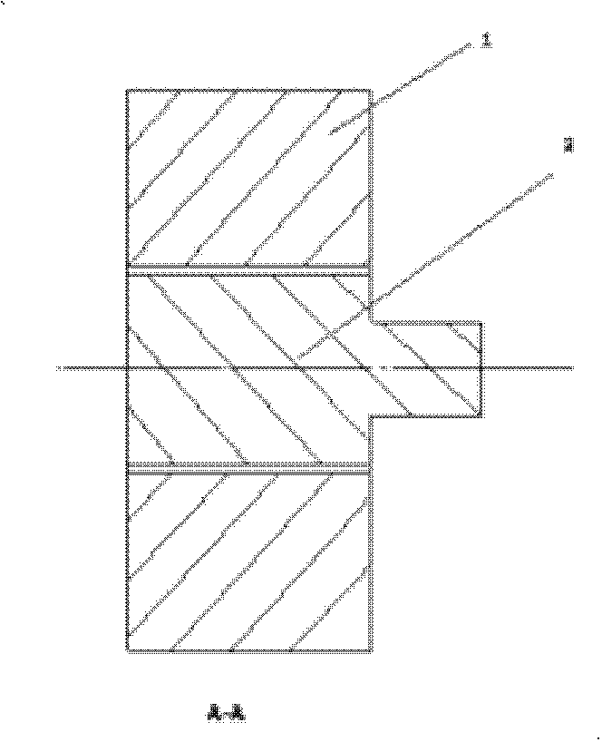

Image

  • Motor, fly-back control method of motor and energy circulation control method of motor
  • Motor, fly-back control method of motor and energy circulation control method of motor
  • Motor, fly-back control method of motor and energy circulation control method of motor

Examples


Embodiment Construction

[0047] In order to describe the technical content, objectives and effects of the present invention in detail, the following descriptions will be made in conjunction with preferred embodiments.

[0048] The invention relates to a new type of ultra-high-efficiency motor that combines flyback motor control technology and energy circulation (regeneration) technology. In the invention, the working principle, structural design, and control mode of the motor are different from traditional motors. , its characteristics and effects are also quite different from traditional motors, especially the motor does not use any permanent magnet materials, so it has great practical significance for energy saving, emission reduction, and protection of rare resources.

[0049] combine figure 2 and image 3 , first introduce the specific structure of the motor of the present invention: the motor includes two parts, a stator 1 and a rotor 2, the stator 1 includes a stator core 11 and a stator coil ...


PUM


Abstract

The invention provides a motor and belongs to the technical field of electric engineering. The motor comprises a stator and a rotor, wherein each stator coil is provided with eighteen pole yokes, the pole yokes of each stator coil are the same in wire diameter and are sequentially connected to be divided into three phases, the adjacent pole yokes of each phase are oppositely connected end to end, and a rotor iron core is provided with six convex pole yokes forming a closed loop of a magnetic field. The structure of the motor meets the condition that the number m of the pole yokes of the stator divided by the number n of the pole yokes of the rotor makes the number q of phases, wherein q is three, and the number n of the pole yokes of the rotor is larger than or equal to three. The invention further provides a fly-back control method based on the motor and an energy circulation control method based on the motor. According to the motor, the fly-back control method of the motor and the energy circulation control method of the motor, the fly-back mode control technology and the energy circulation technology can be utilized properly so that the motor can be ultra low in power consumption and have ultra high efficiency.

Description

technical field [0001] The invention relates to the technical field of electrical engineering, in particular to a motor and its control technology. Background technique [0002] Motor refers to an electromagnetic device that realizes the conversion between mechanical energy and electrical energy according to the law of electromagnetic induction, mainly including generators and motors. A typical motor structure in the prior art usually includes a stator and a rotor. The stator includes a stator core and a stator coil. The stator core is fixed on the base of the motor, and the stator coil is wound on the stator core according to certain rules; the rotor includes a rotor Iron core and rotor coil, the rotor iron core is fixed on the rotating shaft, and the rotor coil is wound on the rotor iron core. In the prior art, the structural design, working principle, and control mode adopted by ordinary permanent magnet motors all restrict the energy efficiency, power consumption, energ...

Claims


Application Information

Patent Timeline
Patent Type & Authority Applications(China)
IPC IPC(8): H02K1/16H02K1/24H02P23/00H02P1/26
Inventor 黄长明缪希泽黄耿民
Owner 宁德市犇田动力有限公司
Learn More