
Adsorption table

A technology of adsorption table and adsorption surface, which is applied in the direction of instruments, electrical components, measuring electronics, etc., can solve the problems of high price, complicated structure of adsorption device, complicated structure of supporting table, etc.

Active Publication Date: 2016-08-17
NIHON MICRONICS
View PDF6 Cites 0 Cited by
  • Summary
  • Abstract
  • Description
  • Claims
  • Application Information

AI Technical Summary

Problems solved by technology

Therefore, the structure of the supporting table forming the adsorption surface is complicated, and it is necessary to arrange a mechanism for making many lifting members go up and down at the inside of the supporting table. Because the structure of the supporting table is complicated, the structure of the adsorption device is complicated. Disadvantages such as high price

Method used


Image

  • Adsorption table
  • Adsorption table
  • Adsorption table

Examples


Embodiment Construction

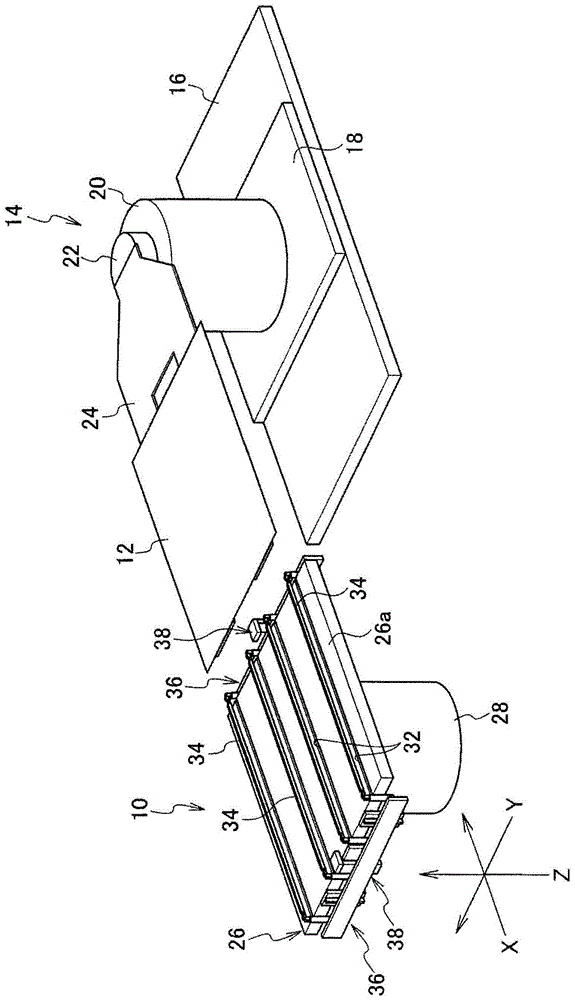
[0038] Such as figure 1 As shown, the suction table 10 of the present invention is assembled and used in a detector (not shown) for inspecting a display panel 12 such as a liquid crystal panel or an organic light emitting panel. exist figure 1 An example in which the inspection object 12 is delivered between the adsorption table 10 and the transfer robot 14 is shown in .

[0039] As known in the past, the delivery robot 14 includes: a movable table 18, which can move toward the adsorption table 10 on the base 16 and move along the direction away from the adsorption table 10; The pillar 20 on the table is coaxially supported by the pillar 20, and the shaft member 22 rotates around the axis and expands and contracts relative to the pillar 20 along the axis. As conventionally known, a fork-shaped robot arm 24 for placing the object 12 to be inspected is fixed to the shaft member 22 capable of the rotational movement and the telescopic movement.

[0040] For example, when the t...


PUM


Abstract

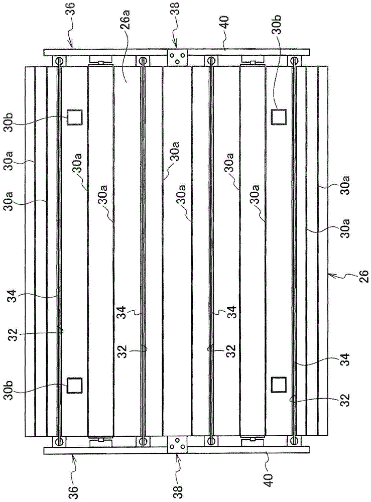
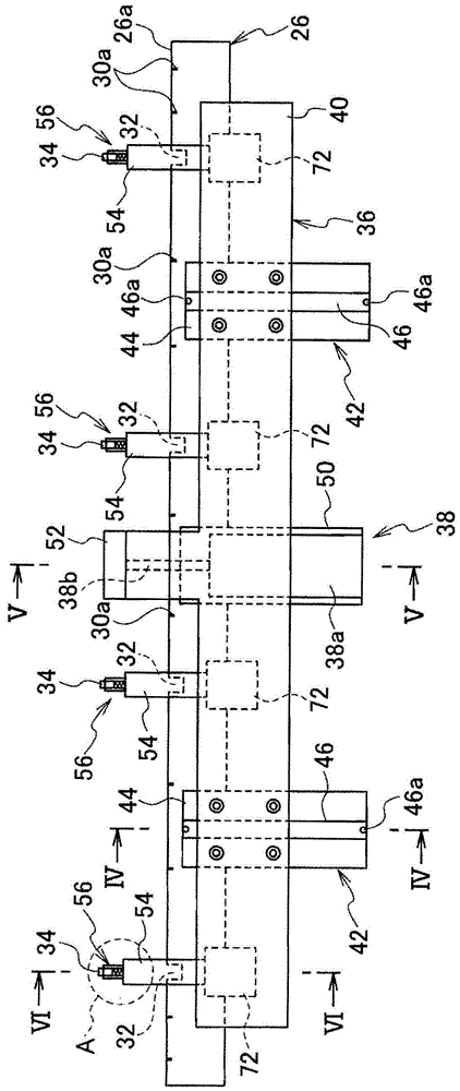
PROBLEM TO BE SOLVED: To provide a suction table which can lift a display panel on a suction surface at delivery without having a complicated configuration nor locally applying strong stress on the display panel.SOLUTION: A suction table holds a display panel and includes a support board having a suction surface in which negative pressure openings open, a plurality of lift bars disposed across the suction surface, a plurality of recesses arranged in parallel with each other on the suction surface so as to house the lift bars in the support board without being protruded form the suction surface, support mechanisms that support the lift bars in a vertically movable manner at sides of the support board in which the plurality of recesses open, and lifting devices arranged in relation with the support mechanisms so as to lift the lift bars between an ascent position where the lift bars are protruded from the recesses and a descent position where the lift bars are housed in the recesses. The support mechanisms comprise support pillars for supporting the lift bars at both ends, guide pins supported by the support pillars, and slots arranged in the lift bars so as to allow the guide pins to penetrate therethrough.

Description

technical field [0001] The present invention relates to an adsorption stand suitable for holding a display panel such as a liquid crystal display panel or an organic light emitting panel. Background technique [0002] For example, in a manufacturing process of a display panel such as a liquid crystal display panel in which a circuit is formed on a glass substrate, the display panel is electrically inspected using a probe. In this test, a liquid crystal display panel, which is an object to be inspected, is usually held by a negative pressure on an adsorption table incorporated in a probe tester. [0003] In order to safely and quickly unload the inspected object from the suction table, the suction table is provided with a plurality of devices for floating the object to be inspected from the suction surface in a manner that can protrude from the suction surface of the suction table. a lift pin (for example, refer to Patent Document 1). [0004] When the lift pin at the protr...

Claims


Application Information

Patent Timeline
Patent Type & Authority Patents(China)
IPC IPC(8): H01L21/683G01R31/00
CPCH01L21/6838H01L2221/68304B65G49/061G02F1/1303H01L21/683
Inventor 白户顺工藤隆善
Owner NIHON MICRONICS
Learn More