Method for Measuring Response Time of Dynamic Var Generator with Unified Time Scale

A technology of generating device and response time, which is applied to the device for measuring time interval, electrical unknown time interval measurement, measuring device and other directions, which can solve the problems of inaccurate measurement of response time of dynamic reactive power generating device and so on.

Active Publication Date: 2016-03-30
STATE GRID CORP OF CHINA +1
View PDF5 Cites 0 Cited by
  • Summary
  • Abstract
  • Description
  • Claims
  • Application Information

AI Technical Summary

Problems solved by technology

[0003] The invention provides a method for measuring the response time of a dynamic reactive power generating device with a unified time scale, which solves the problem of inaccurate measurement of the response time of the dynamic reactive power generating device existing in the prior art

Method used


Image

  • Method for Measuring Response Time of Dynamic Var Generator with Unified Time Scale
  • Method for Measuring Response Time of Dynamic Var Generator with Unified Time Scale
  • Method for Measuring Response Time of Dynamic Var Generator with Unified Time Scale

Examples


Embodiment Construction

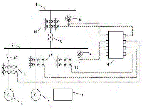
[0020] A device for measuring the response time of a dynamic reactive power generating device with a unified time scale, including a high-voltage side bus 1, a low-voltage side bus 2, a dynamic reactive power generating device 3 and a waveform recorder 4, and a transformer is electrically connected to the high-voltage side bus 1 5. The voltage transformer 6 on the high-voltage side is electrically connected to the bus bar 2 on the low-voltage side with the first collector line 7, the second collector line 8, the dynamic reactive power generating device 3 and the voltage transformer 9 on the low-voltage side. A circuit breaker 10 is arranged between the bus bar 2 and the first collector line 7, a first collector circuit current transformer 11 is arranged on the first collector circuit 7, and the secondary side of the first collector circuit current transformer 11 Phase A is electrically connected to the second current waveform input terminal of the waveform recorder 4, and the s...


PUM


Abstract

The invention discloses a time scale unified dynamic reactive power generating device response time detecting method. The time scale unified dynamic reactive power generating device response time detecting method solves the problem that detection on the dynamic reactive power generating device response time is inaccurate in the prior art. According to the time scale unified dynamic reactive power generating device response time detecting method, a high voltage side bus, a low voltage side bus, the dynamic reactive power generating device and a waveform recorder are included, a secondary side phase A of a first current collection circuit current transformer (11) is electrically connected to a second current waveform input terminal of the waveform recorder (4), and the sampling of response current waveforms and response voltage waveforms is completed by operating a breaker (10). A response time calculation model is established in a computer by using a discrete data calculation effective value tool, calculation time is set as 800 milliseconds, a voltage effective value curve (15) and a current effective value curve (16) of a smooth response process are generated, and accurate dynamic reactive power generating device response time is obtained. The time scale unified dynamic reactive power generating device response time detecting method can calculate the dynamic reactive power generating device response time accurately, and is especially suitable for field service in a power grid.

Description

technical field [0001] The invention relates to a method for measuring the response time of a dynamic reactive power generation device connected in a power grid to system voltage disturbances. Background technique [0002] After the large-scale connection of wind farms to the power grid, the application of a large number of power electronic devices has caused new problems to the power grid, especially the large-scale disconnection of wind power, which will have a serious impact on the power grid. In order to ensure the safe and stable operation of the system, new requirements are put forward for the response time of the wind farm dynamic reactive power generator. According to the relevant requirements, the response time of the dynamic reactive power generating device in the wind farm should be within 30 milliseconds, which requires effective and true measurement of the response time of the dynamic reactive power generating device on site, so as to determine the dynamic react...

Claims


Application Information

Patent Timeline
Patent Type & Authority Patents(China)
IPC IPC(8): G04F10/04G01R31/00
Inventor 杨超颖王康宁王金浩徐龙雷达肖莹齐月文仇汴宋述勇张悦弥勇曹静杜慧杰吴玉龙
Owner STATE GRID CORP OF CHINA
Why Eureka
Try Eureka