Lens drive device, automatic focusing camera and mobile terminal with camera

A lens driving device and lens technology, which is applied to cameras, focusing devices, electromechanical devices, etc., can solve problems such as easy deviation

Active Publication Date: 2014-03-26
NEW SHICOH MOTOR CO LTD
View PDF4 Cites 0 Cited by
  • Summary
  • Abstract
  • Description
  • Claims
  • Application Information

AI Technical Summary

Problems solved by technology

[0004] However, when assembling the lens driving device, in order to smoothly insert the leaf spring member between the columnar portions, a certain amount of clearance is required between the outer portion of the leaf spring member and the columnar portion.
Once there is such a gap, it is easy to cause a problem of deviation in the positioning position of the leaf spring member and the base member

Method used


Image

  • Lens drive device, automatic focusing camera and mobile terminal with camera
  • Lens drive device, automatic focusing camera and mobile terminal with camera
  • Lens drive device, automatic focusing camera and mobile terminal with camera

Examples


Embodiment Construction

[0050] Hereinafter, embodiments of the present invention will be described with reference to the drawings.

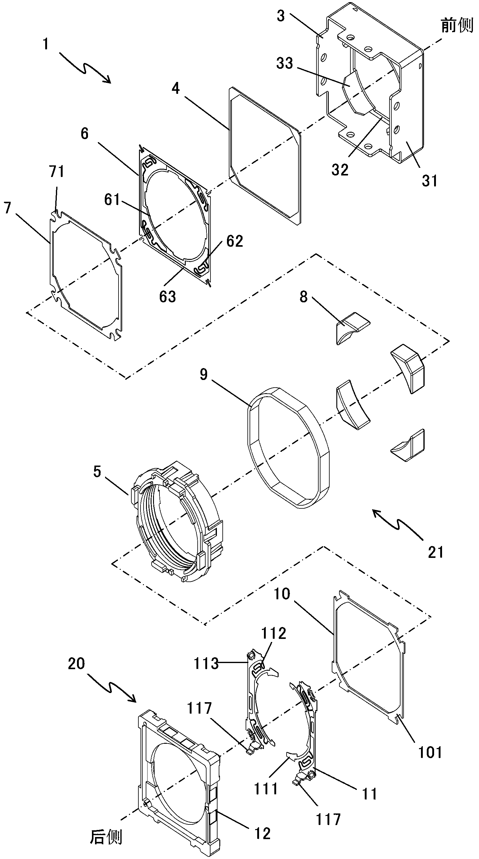
[0051] The lens driving device 1 in this embodiment is a lens driving device used in an auto-focus camera device incorporated in a camera-equipped mobile terminal device typified by a cellular phone and a smart phone.

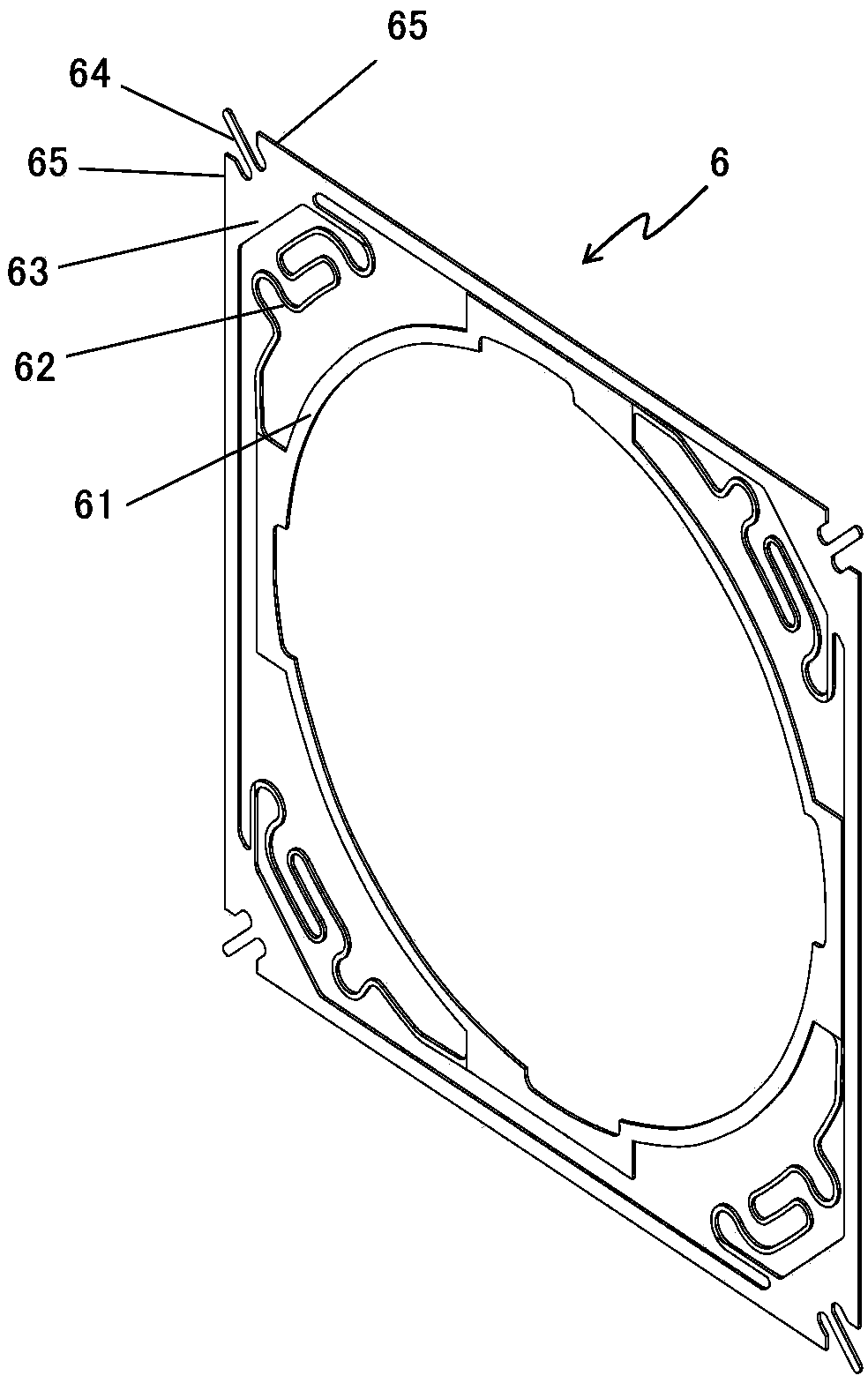
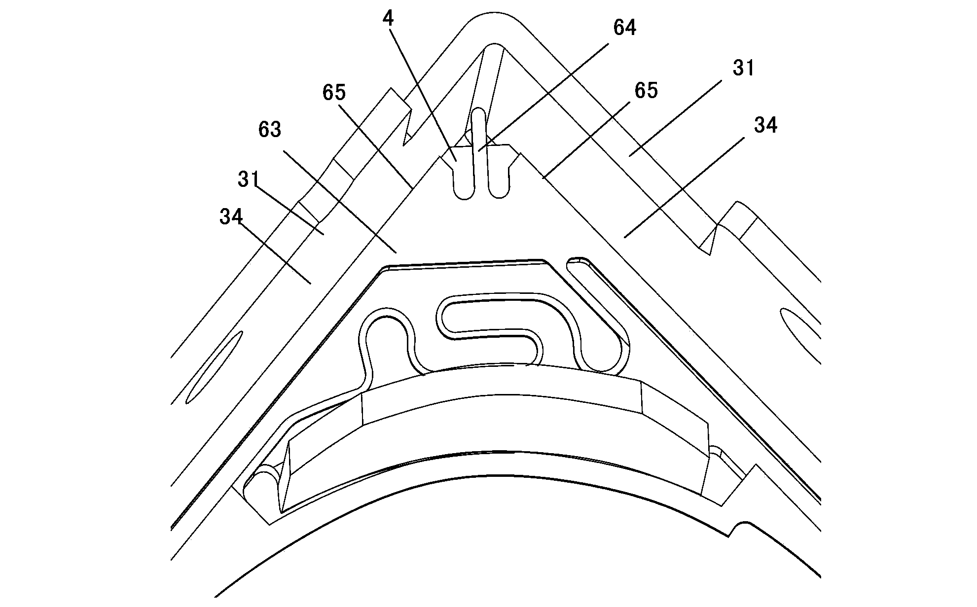
[0052] This lens driving device 1 such as figure 1 As shown, a lens support body 5 , a fixing part 20 , a drive mechanism 21 , and leaf spring members 6 and 11 are included. The lens support body 5 supports a lens (not shown) movably in the direction of its optical axis. The fixing part 20 is disposed on the outer peripheral side of the lens support body 5. The drive mechanism 21 moves the lens support body 5 in the direction of the optical axis. The leaf spring members 6, 11 have inner parts 61, 111 fixed to the lens support body 5 , the outer part 63, 113 fixed on the fixing part 20, and the plurality of arm parts 62, 112 connecting the inner part 6...


PUM


Abstract

The invention aims at providing a lens drive device with good positioning accuracy, an automatic focusing camera and a mobile terminal with the camera when a plate spring part material is assembled. The lens drive device comprises a lens supporting body for movably supporting a lens in the direction of an optical axis, a fixing part configured on the peripheral side of the lens supporting body, a drive mechanism for moving the lens supporting body in the direction of the optical axis, and the plate spring part material with an inner side part fixed to the lens supporting body, an outer side part fixed to the fixing part and a plurality of wrist parts for connecting the inner side part with the outer side part. The lens drive device is characterized in that the fixing part is provided with a vertical wall part which is polygonal in the direction of the optical axis and is vertically arranged in the direction of the optical axis and used for containing the plate spring part material on the inner side; tongue parts extending to the outer side are arranged at the outer side part of the plate spring part material in correspondence to the corners of the vertical wall part, are in contained states on the inner side of the vertical wall part, are butted with the corners of the vertical wall part, and can be elastically deformed in the direction of the optical axis.

Description

technical field [0001] The present invention relates to a related lens driving device, an auto-focus camera device equipped with the lens driving device, and a mobile terminal device with a camera function equipped with the auto-focus camera. Background technique [0002] The lens driving device used in the auto-focus camera assembled in the mobile terminal device with camera includes: a cylindrical lens support body, which holds the lens; a coil, fixed on the periphery of the lens support body; a cylindrical ring mouth, configured On the outer circumference of the coil; the magnet is fixed on the inner circumference of the ring mouth and the coil, and is arranged facing each other; the plate spring member supports the lens supporting body movably in the direction of the optical axis of the lens. These parts are built on the base. Then, this lens driving device moves the lens support in the direction of the optical axis of the lens based on the electromagnetic force generat...

Claims


Application Information

Patent Timeline
IPC IPC(8): G02B7/09G03B13/36H02K33/18
Inventor 白木学三轮哲久
Owner NEW SHICOH MOTOR CO LTD
Why Eureka
Try Eureka