Mechanical pressing device and optical-fiber connecting device

A compression device and optical fiber connection technology, which is applied in the field of optical communication, can solve problems such as insufficient straightness and flatness, low product yield, and defective products, and achieve the effect of saving labor costs and improving the yield rate

Active Publication Date: 2014-03-26
SHENZHEN ZHAOWEI MACHINERY&ELECTRONICS CO LTD
View PDF3 Cites 1 Cited by
  • Summary
  • Abstract
  • Description
  • Claims
  • Application Information

AI Technical Summary

Problems solved by technology

If the gap between the pressure plate and the V-shaped groove is too small, the fiber will be scratched during the insertion process, resulting in the cross-sections of the two optical fibers not being in contact; if the gap between the pressure plate and the V-shaped groove is too large, it will cause The optical fiber may be inserted outside the V-shaped groove, resulting in serious defects; if the straightness and flatness of the V-shaped groove are not enough, it will cause dislocation of the optical fiber in the butt joint of the V-shaped groove; if the optical fiber is under too much pressure, the If the optical fiber is under too little pressure, it will cause the optical fiber to be unable to be compressed and loosen. Therefore, the standard for pulling out the optical fiber is 3N-5N.
[0004] In the prior art, the injection mold of the V-groove substrate is machined by electric spark discharge, which results in a flat end face of the V-groove substrate and poor dimensional accuracy, resulting in either too large or too small a gap between the V-groove substrate and the V-groove compact. As a result, the pressure received by the optical fiber is either too large or too small, and the use of EDM leads to poor consistency of each piece of processing, and the product yield is low, especially the straightness of the V-shaped groove processed by EDM Insufficient smoothness and smoothness, resulting in misalignment of optical fibers in the butt joint of V-groove
On the other hand, in the prior art, the fiber guide holes at both ends of the V-groove substrate and the V-groove pressing block are semi-conical. The guide slope also has the problems of uneven surface, split line and edge. When the optical fiber is inserted into the V-groove, it contacts with the tapered guide slope of the fiber guide hole, which is easy to cause glue shoveling, resulting in gaps between the butt optical fibers. Causes the insertion loss rate of the fiber to increase

Method used


Image

  • Mechanical pressing device and optical-fiber connecting device
  • Mechanical pressing device and optical-fiber connecting device
  • Mechanical pressing device and optical-fiber connecting device

Examples


Embodiment

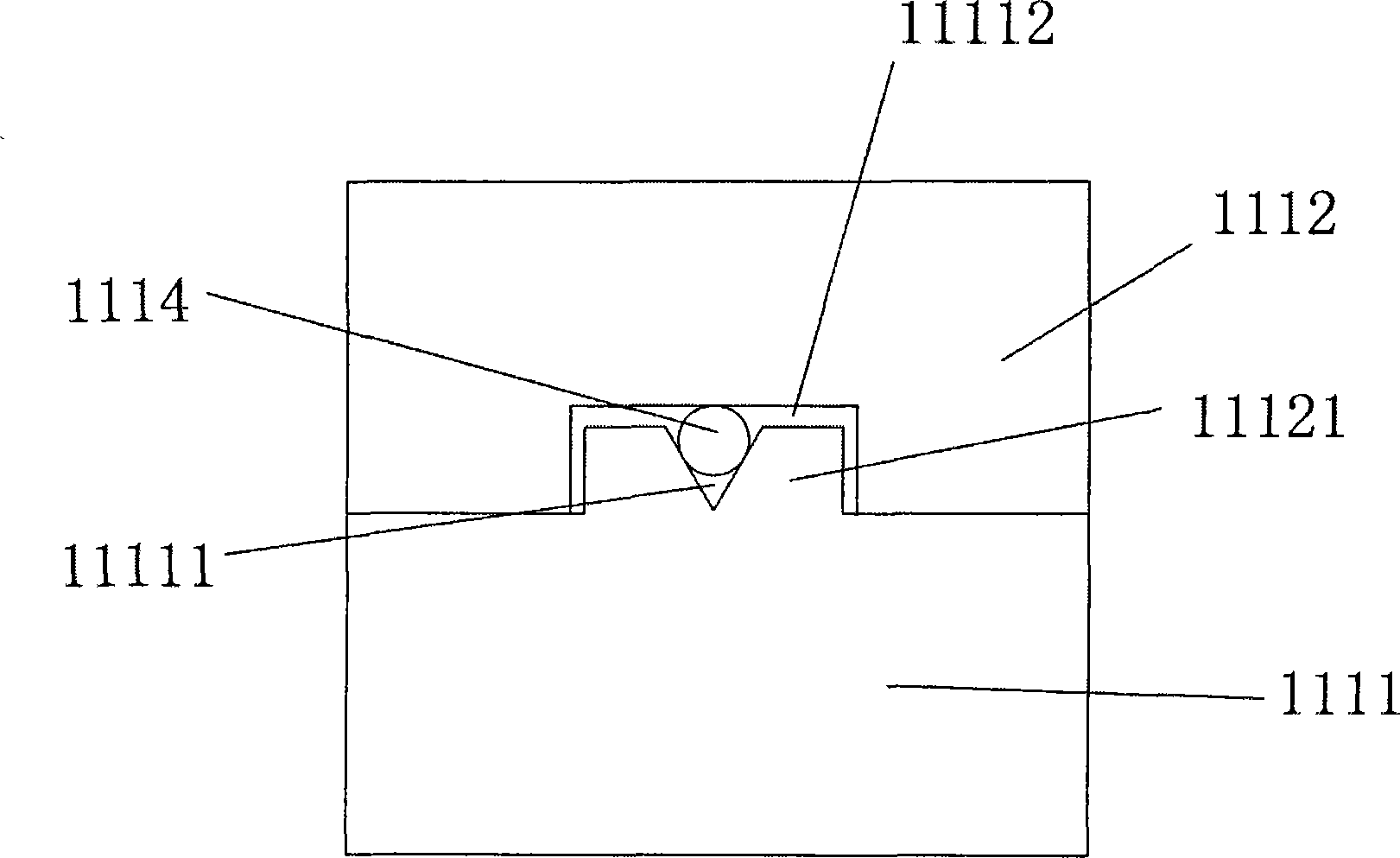
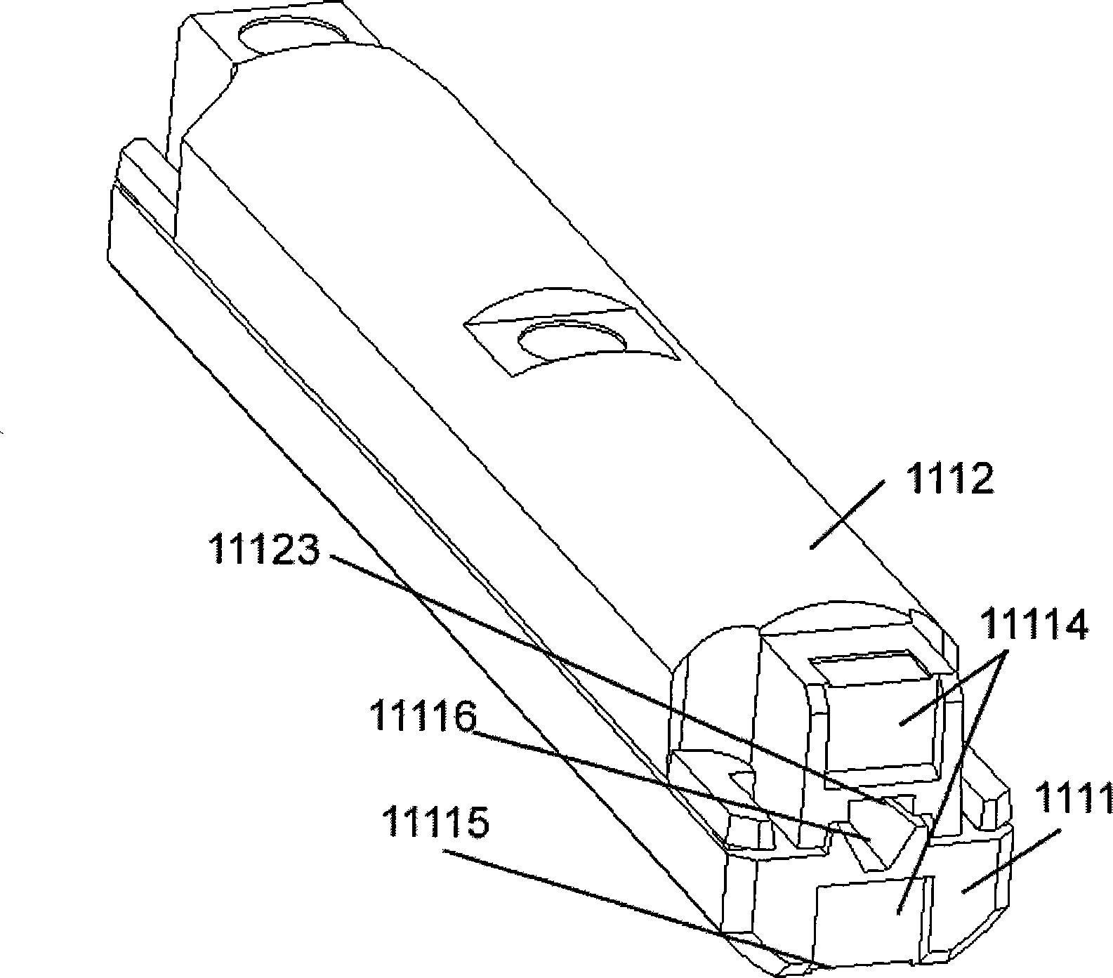
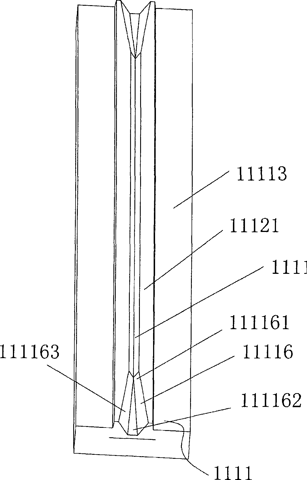
[0034] This embodiment provides another mechanical compression device of an optical fiber connection device and an optical fiber connection device having the mechanical compression device. Such as Figure 1-8 As shown, the optical fiber connection device 10 includes a main body 11 with a hollow structure and a jacket 12 arranged on the periphery of the main body. A mechanical pressing device 111 is provided inside the main body 11. The mechanical pressing device 111 includes a V-groove base plate 1111, The V-groove base plate 1111 has a V-shaped groove 11111 for embedding optical fiber ferrules, a V-groove pressing block 1112, a fixed sleeve 1115 and a sliding pressing sleeve 1113, and the V-groove base plate 1111 and the V-groove pressing block 1112 are fixed Inside the cavity of the sleeve, the sliding press sleeve 1113 is sleeved on the outside of the fixed sleeve, one side of the V-groove base plate 1111 is provided with a boss 11121, and one side of the V-groove pressing ...


PUM


Abstract

The invention discloses a mechanical pressing device of an optical-fiber connecting device and the optical-fiber connecting device provided with the mechanical pressing device. Disclosed is the mechanical pressing device of the optical-fiber connecting device. The mechanical pressing device includes a V-groove substrate. The V-groove substrate is provided with a V-shaped groove used for burying an optical-fiber insert core, a V-groove press block, a fixed sleeve and a sliding pressing sleeve. The V-groove substrate and the V-groove press block are arranged in a cavity of the fixed sleeve. The sliding pressing sleeve is sleeved outside the fixed sleeve. The mechanical pressing device is characterized in that the V-groove substrate cooperates with the V-groove press block through a groove; a boss is in cooperation with the groove; the V-shaped groove is arranged on the boss or in the groove; and when the V-groove substrate and the V-groove press block contact, the boss contacts the optical-fiber insert core. Even if the V-groove substrate and the V-groove press block are subjected to extrusion, faces which bear the force first are step faces of the V-groove substrate and the V-groove press block so that a problem that the optical-fiber insert core in the V-shaped groove is overly pressed is prevented.

Description

【Technical field】 [0001] The invention belongs to the technical field of optical communication, and relates to a mechanical compression device of an optical fiber connection device and an optical fiber connection device with the mechanical compression device. 【Background technique】 [0002] After the optical cable enters the cabinet, the optical signal is sent to each user through the optical splitter. The user connects the signal to the optical modem through the optical fiber network cable. The optical modem couples the optical signal into an electrical signal and transmits it to the computer through the ordinary network cable. The docking is to insert the fiber optic quick connector into the precision positioning sleeve on the optical cat. When connecting, the interface between the two optical fibers should be very flat. At the same time, because the diameter of the optical fiber is very thin, no matter whether the optical fiber is inserted into the optical cat or the opti...

Claims


Application Information

Patent Timeline
Patent Type & Authority Applications(China)
IPC IPC(8): G02B6/36G02B6/38
Inventor 陆志强梁芝明沈亚强袁小林
Owner SHENZHEN ZHAOWEI MACHINERY&ELECTRONICS CO LTD
Why Eureka
Try Eureka