
Angle sensor

An angle sensor and housing technology, applied in the direction of instruments, using electric/magnetic devices to transmit sensing components, measuring devices, etc., can solve problems such as prone to errors, hidden dangers of driving safety, and low product reliability, and meet the needs of gears Signal output requirements, improved reliability and durability, and the effect of overcoming mechanical loss

Inactive Publication Date: 2014-03-26
HAMLIN ELECTRONIC (SUZHOU) CO LTD
View PDF9 Cites 2 Cited by
  • Summary
  • Abstract
  • Description
  • Claims
  • Application Information

AI Technical Summary

Problems solved by technology

However, due to the use of contact coding in this patent, errors are prone to occur, the product reliability is not high, and the analog output of the gear position signal cannot be realized, which brings safety hazards to driving

Method used


Image

  • Angle sensor
  • Angle sensor
  • Angle sensor

Examples


Embodiment

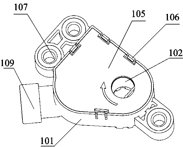
[0018] An angle sensor of this embodiment, such as Figure 3-Figure 4 As shown, a housing 101 is included. One side of the housing 101 has an open space, and a rotor 102 and a Hall chip 103 are arranged in the open space. A magnet 104 is arranged on the rotor 102 , and the magnet 104 is biased relative to the Hall chip 103 . The rotating shaft of the gearbox PRND handle matches the rotor 102 and drives the rotor 102 to rotate. It also includes an upper cover 105 corresponding to the housing 101 , and the upper cover 105 closes the open space through a buckle structure 106 . A plurality of fixed copper sleeves 107 are provided on the outer wall of the housing 101 . The Hall chip 103 is installed on the circuit board 108 , and the circuit board 108 protrudes out of the housing 101 through the plug 109 .

[0019] When applying this embodiment, the rotating shaft of the PRND handle of the gearbox drives the rotor 102 to rotate, and then drives the magnet 104 to rotate, and the H...


PUM


Abstract

The invention discloses an angle sensor which comprises a shell. One side face of the shell is provided with an open space, a rotor and a Hall chip are arranged in the open space, a magnet is disposed on the rotor, and the magnet is bias relative to the Hall chip. A non-contact structure is adopted, a bias structure is adopted on the Hall chip relative to the magnet, mechanical loss caused by mechanical friction is overcome, reliability and durability of products are improved, gear signal output requirements can be met, and analog or digital output is achieved.

Description

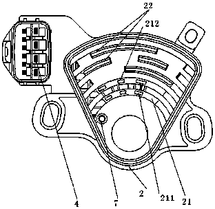
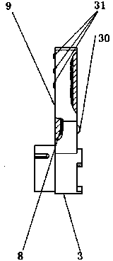
technical field [0001] The invention relates to an angle sensor, in particular to an angle sensor used for detecting the position of each gear position of a PRND handle on a gearbox. Background technique [0002] Chinese patent 201020650886.1 discloses a contact gear sensor, such as figure 1 and 2 As shown, it includes the lower casing 2, the rotor 3 and the pins 4. The lower casing 2 includes two guide rails 21 for starting and reverse gears, at least three guide rails 22 for gear positions, and a piece of metal elastic body 7. Each gear The position guide rail 22 and the two start and reverse guide rails 21 are concentric and arranged in parallel and insulated at intervals; the two start and reverse guide rails 21 respectively include a start contact section 211 and a reverse contact section 212 separated by an insulator ; Each gear guide rail 22 is divided into one or more guide sections electrically connected under the insulator respectively by the insulator, wherein a...

Claims


Application Information

Patent Timeline
Patent Type & Authority Applications(China)
IPC IPC(8): G01B7/30G01D5/12
Inventor 赵建飞褚贵庭
Owner HAMLIN ELECTRONIC (SUZHOU) CO LTD
Learn More