Coupling
A technology of coupling and rotating shaft, applied in the direction of coupling, elastic coupling, mechanical equipment, etc., can solve problems such as enlargement, achieve the effect of reducing load, realizing miniaturization, and realizing assembly workability
- Summary
- Abstract
- Description
- Claims
- Application Information
AI Technical Summary
Problems solved by technology
Method used
Image
Examples
Deformed example (1
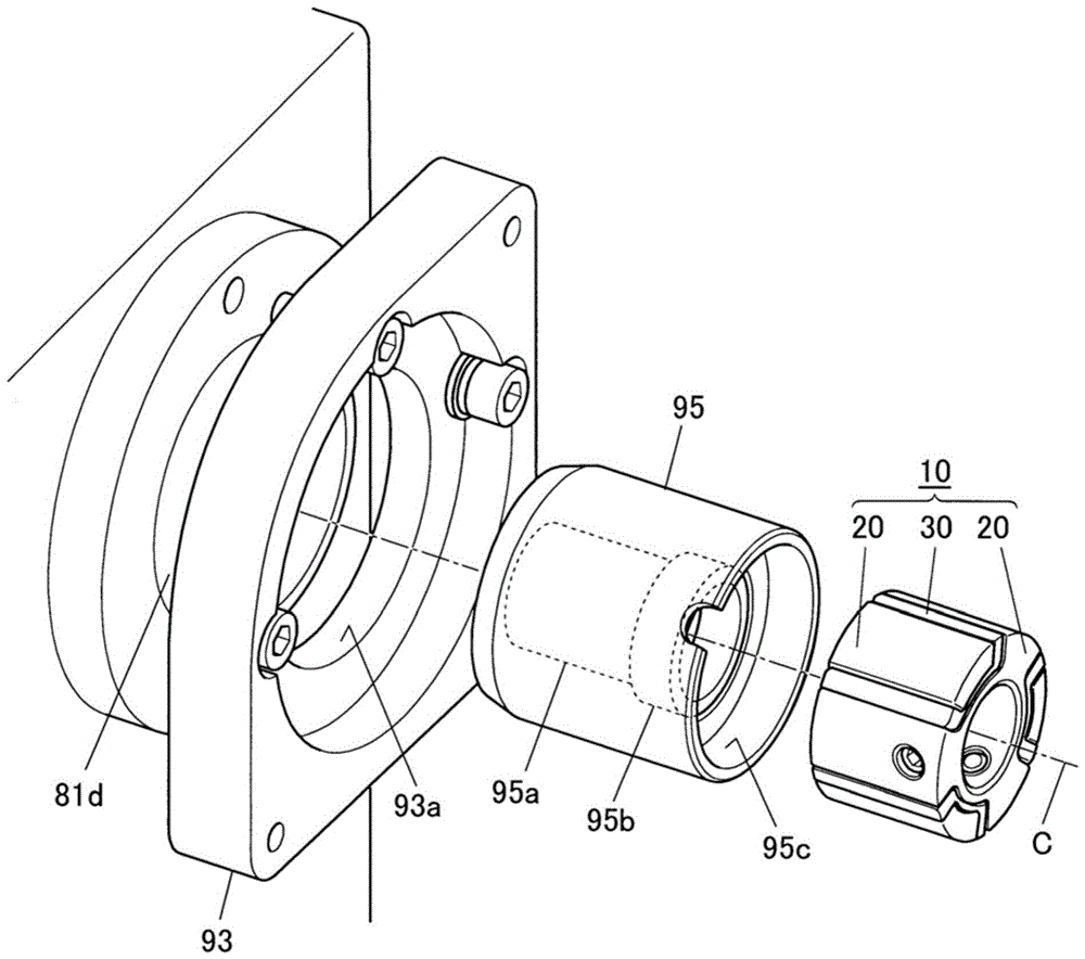
[0137] Figure 7 It is an exploded perspective view of the first modified example of the coupling. In this coupling 10A, the structure other than the connecting member 30A may be the same as that of the coupling 10 .
[0138] The connection member 30A of the shaft coupling 10A has: the same six insertion parts 31 as the connection member 30; The other end portion is alternately connected; and the same partition wall portion 33 as the connection member 30 . Furthermore, this connecting member 30A is also integrally formed of rubber which is an elastic body, for example, nitrile rubber (NBR).
[0139] In addition, each connecting portion 32A is formed in a shape that follows the end surface of the extending end portion of the extending portion 23 of the boss 20 at one end or the other end of the connected two insertion portions 31 . In addition, it is preferable to shorten the protruding length of each extension portion 23 corresponding to the thickness of the connection port...
Deformed example (2
[0143] Figure 8 It is a perspective view of the second modified example of the coupling. In this coupling 10B, the structure other than the connecting member 30B may be the same as that of the coupling 10 .
[0144] The connection member 30B of the coupling 10B separates the six insertion portions 31B inserted between the protrusions 22 of the two bosses 20 , 20 , and does not have the connection portion 32 and the partition wall portion 33 .
[0145] In addition, in the manufacturing process of the coupling 10B, each insertion portion 31B is fastened to one or both of the two opposing side surfaces of the adjacently provided bosses 22 , 22 by bonding, sintering, or the like. on both.
[0146] Each insertion portion 31B cannot be separated from the boss 20 while being fastened to one side surface of each boss portion 22 . Moreover, when fastening to two side surfaces of each boss part 22, two bushings 20, 20 and the connection member 30B are integrated and cannot be separa...
Deformed example (3
[0151] Figure 9 It is a perspective view of a third modified example of the coupling. In this coupling 10C, the structure other than the boss 20C can be set to be the same as that of the coupling 10 .
[0152] In the above-mentioned shaft coupling 10, the length of the extension portion 23 of each sleeve 20 in the direction of the rotation center line C is set to be approximately equal to the length of the main body portion 21, thus, the total length of the boss portion 22 = shaft coupling The full length of device 10. By making the aforementioned lengths uniform, the contact area between the boss portion 22 and the insertion portion 31 can be maximized relative to the size of the coupling 10 .
[0153] On the other hand, the extension part 23C of each boss 20C of the joint 10C is set to be shorter in the direction of the rotation center line C than the main body part 21 . Therefore, the total length of the boss 22 Figure 11 , Figure 12 ), the load per unit area in each ...
PUM
 Abstract
Description
Claims
Application Information
 - R&D
- Intellectual Property
- Life Sciences
- Materials
- Tech Scout
- Unparalleled Data Quality
- Higher Quality Content
- 60% Fewer Hallucinations
Browse by: Latest US Patents, China's latest patents, Technical Efficacy Thesaurus, Application Domain, Technology Topic, Popular Technical Reports.
© 2025 PatSnap. All rights reserved.Legal|Privacy policy|Modern Slavery Act Transparency Statement|Sitemap|About US| Contact US: help@patsnap.com


